© 2020 Carrier
21
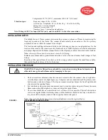
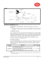
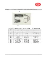
FIGURE 16.
WIRING FOR 95UVS4-1CEX and 95IRS4-1CEX scanners (shown with housing cover removed))
Connector
Pin
Function for -1 Version
Function for -2 Version
59-547 Cable Color (if used)
Terminal Block 1 (TB1)
TB1-1
RFS2
Flame Relay NC
Black/Yellow stripe
TB1-2
RFS1
RFS1
Blue/Black stripe
TB1-3
Comm (A)
Comm (A)
Brown/Orange stripe
TB1-4
Comm (B)
Comm (B)
Orange/Black stripe
TB1-5
4-20mA (+)
4-20mA (+)
Red/White stripe
TB1-6
4-20mA (-)
4-20mA (-)
Black / Orange stripe
TB1-7
24V Supply (-)
24V Supply (-)
Yellow/Black stripe
TB1-8
24V Supply (+)
24V Supply (+)
Blue/Red stripe
Terminal Block 2 (TB2)
TB2-1
Fault Relay NC
Fault Relay NC
Brown/Black stripe
TB2-2
Fault Relay COM
Fault Relay COM
Red/Black stripe
TB2-3
Flame Relay COM
Flame Relay COM
Orange/White stripe
TB2-4
Flame Relay NO
Flame Relay NO
Violet/White stripe
TB1
TB2
Summary of Contents for InSight 4 Series
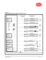
Page 19: ... 2020 Carrier 19 Figure 14 WIRING DIAGRAM 95UVS4 1 95IRS4 1 with 59 547 cable ...
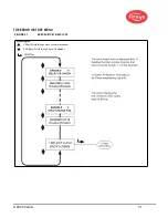
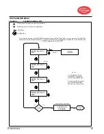
Page 27: ... 2020 Carrier 27 THE MAIN STATUS MENU FIGURE 20 MAIN STATUS MENU LOOP ...
Page 36: ... 2020 Carrier 36 THE CONFIG MENU FIGURE 23 CONFIG MENU LOOP ...
Page 40: ... 2020 Carrier 40 THE AUTO CONFIG MENU FIGURE 25 AUTO CONFIG MENU LOOP ...
Page 43: ... 2020 Carrier 43 THE FILE COPY MENU FIGURE 26 FILE COPY MENU LOOP ...
Page 45: ... 2020 Carrier 45 THE 4 20 mA MENU FIGURE 27 4 20mA MENU LOOP ...
Page 47: ... 2020 Carrier 47 THE DATE TIME MENU FIGURE 28 DATE TIME MENU LOOP ...
Page 49: ... 2020 Carrier 49 THE COMMS MENU FIGURE 29 COMMS MENU ...
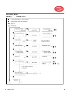
Page 51: ... 2020 Carrier 51 THE MANUAL CONFIG MENUS FIGURE 30 ...
Page 52: ... 2020 Carrier 52 MANUAL CONFIG MENUS continued FIGURE 31 ...

