© 2020 Carrier
46
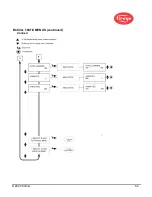
THE 4/20 mA MENU
FR 4/20 SELECT
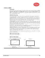
The user may select which parameter the 4-20 mA analog output represents. Choices are
Flame
QUALITY, Flame SIGNAL, or FRONT END GAIN
. Factory default is
Flame QUALITY
. Press
SELECT to enter option; Use UP or DOWN key to pick Flame QUALITY, Flame SIGNAL, or Track
FEG; press PROGRAM to SAVE.
FR 20mA MAP VAL (Range)
This option allows the user to select the 4-20 mA range (MAP VAL) of the parameter selected above.
If
Flame QUALITY
was selected, the analog output will be 4 mA when the FQ=0. The range, or
Flame Quality value for 20 mA (20mA MAP VAL), is user selectable anywhere between 40 and 100.
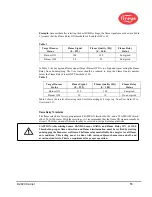
The factory default value is 100 (see Example 1 below). If the user selects a value of 50, when the
Flame Quality reaches 50, the analog output will be 20 mA (see Example 2 below).
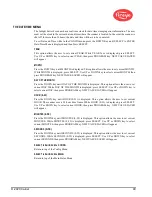
If
Flame SIGNAL
was selected, the analog output will be 4 mA when the flame signal is 000. The
range, or Flame Signal value for 20 mA (20mA MAP VAL), is user selectable anywhere between 400
and 999. The factory default is 999. If the user selects a MAP VAL of 500, when the Flame Signal
reaches 500, the analog output will be at 20 mA.
Press SELECT to enter option and then use UP or DOWN key to pick MAP Value (between 40-100
for FQ, or between 400-999 for FS), then press PROGRAM to SAVE.
If
FRONT END GAIN
was selected, the analog output will be 4 mA when the real time FEG value is
255. The range, or FEG value for 20 mA (20mA MAP VAL) is user selectable anywhere between 5
and 100. The factory default value is 5. If the user selects a MAP VAL of 50, when the FEG value
drops to 50, the analog output will be 20 mA.
Note: The 4-20 mA output is an inverse proportion to the FEG value (e.g., 4 mA at FEG = 255, 20 mA
at FEG = 5 (default value).
SELECT to Exit to Previous Menu
Return to top of the Config Menu
SELECT to Exit BACK to MAIN
Return to top of the Main Status Menu
Example 1
20mA
20mA
Example 2
4mA
0
100
Select = FQ
Map Value = 100
4mA
0
50
Select = FQ
Map Value = 50
100
Summary of Contents for InSight 4 Series
Page 19: ... 2020 Carrier 19 Figure 14 WIRING DIAGRAM 95UVS4 1 95IRS4 1 with 59 547 cable ...
Page 27: ... 2020 Carrier 27 THE MAIN STATUS MENU FIGURE 20 MAIN STATUS MENU LOOP ...
Page 36: ... 2020 Carrier 36 THE CONFIG MENU FIGURE 23 CONFIG MENU LOOP ...
Page 40: ... 2020 Carrier 40 THE AUTO CONFIG MENU FIGURE 25 AUTO CONFIG MENU LOOP ...
Page 43: ... 2020 Carrier 43 THE FILE COPY MENU FIGURE 26 FILE COPY MENU LOOP ...
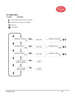
Page 45: ... 2020 Carrier 45 THE 4 20 mA MENU FIGURE 27 4 20mA MENU LOOP ...
Page 47: ... 2020 Carrier 47 THE DATE TIME MENU FIGURE 28 DATE TIME MENU LOOP ...
Page 49: ... 2020 Carrier 49 THE COMMS MENU FIGURE 29 COMMS MENU ...
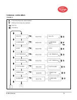
Page 51: ... 2020 Carrier 51 THE MANUAL CONFIG MENUS FIGURE 30 ...
Page 52: ... 2020 Carrier 52 MANUAL CONFIG MENUS continued FIGURE 31 ...


