background image


8


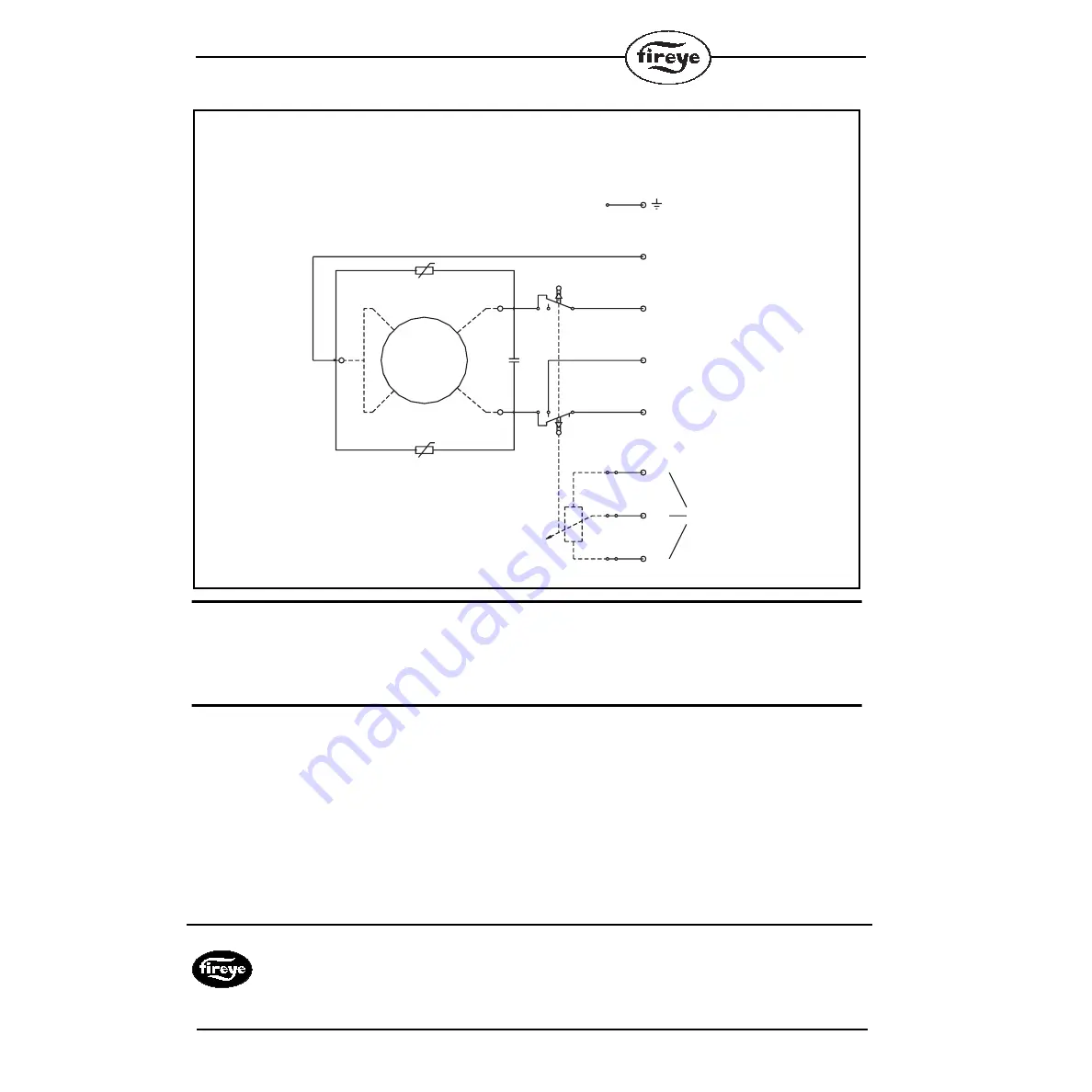
FIGURE 5.

WIRING DIAGRAM NX04 SERVO MOTOR


NOTICE


When Fireye products are combined with equipment manufactured by others and/or integrated into
systems designed or manufactured by others, the Fireye warranty, as stated in its General Terms and
Conditions of Sale, pertains only to the Fireye products and not to any other equipment or to the
combined system or its overall performance.


WARRANTIES


FIREYE guarantees for 


one year from the date of installation or 18 months from date of manufacture


of its products to replace, or, at its option, to repair any product or part thereof (except lamps, elec-
tronic tubes and photocells) which is found defective in material or workmanship or which otherwise
fails to conform to the description of the product on the face of its sales order. 


THE FOREGOING

IS IN LIEU OF ALL OTHER WARRANTIES AND FIREYE MAKES NO WARRANTY OF
MERCHANTABILITY OR ANY OTHER WARRANTY, EXPRESS OR IMPLIED.


 Except as

specifically stated in these general terms and conditions of sale, remedies with respect to any product
or part number manufactured or sold by Fireye shall be limited exclusively to the right to replace-
ment or repair as above provided. In no event shall Fireye be liable for consequential or special dam-
ages of any nature that may arise in connection with such product or part.

TERMINAL 1

1 NEUTRAL

2 DIRECTION 1

L/N/C

3 DIRECTION 2

TERMINAL 2

1

5

2

6

3

7

POTENIOMETER

P1

M2

M3

M

AC


FIREYE 

NX-2004

3 Manchester Road

APRIL 2000

Derry, New Hampshire 03038 USA
www.Fireye.com

Summary of Contents for NEXUS NX04-1

Page 1: ...engineers or personnel qualified by training and experience After installation is complete check the product operation is as described in these instructions The manufacturer of this equipment accepts...

Page 2: ...taneously to the terminals for open and close Fig 3 uncontrollable move ment of the output drive shaft may occur depending on the load on the shaft This situation must be prevented by the user by an e...

Page 3: ...SERVO MOTOR DESCRIPTION FIGURE 1 3 2 1 Plastic Cover 2 Mounting Holes 3 Locating Spigot 4 Output Shaft 5 Plug PG9 6 Cable Entry 7 Limit Switch Cams x 2 8 Plastic Housing 9 Potentiometer 1 9 8 7 6 5 4...

Page 4: ...and control cables by suitably removing sheaths and insulation Feed cables through screwed cable entry via suitable conduit and glands and place the stripped ends of the leads into screw connection t...

Page 5: ...ns the servo motor runs up against a mechanical stop the motor will stall and make a humming noise When this happens the power supply for this direction of operation should be switched off To change t...

Page 6: ...rvo motor the Safety Information on Page 2 and Safety advice in Section 2 must have been read Switch on the power supply to the servo motor Drive the servo motor via the controller or by hand and chec...

Page 7: ...7 FIGURE 4 DIMENSIONS NX04 SERVO MOTOR...

Page 8: ...in material or workmanship or which otherwise fails to conform to the description of the product on the face of its sales order THE FOREGOING IS IN LIEU OF ALL OTHER WARRANTIES AND FIREYE MAKES NO WAR...

Reviews: