10
1.
Cut a hole in the burner front plate in the location desired or as indicated on the installation
drawing. The diameter of the hole should be slightly larger than the outer diameter of the
mounting tube.
2.
Insert the mounting tube through the front plate and into the burner area. Position the mounting
tube to the correct distance and angle shown on the installation drawing.
3.
Seal-weld the mounting tube to the burner front plate using a 6011 weld rod (carbon steel to car-
bon steel) with a full penetration weld. On some older installations where cast iron plates must
be penetrated, a steel flange or cover plate can be bolted to the cast iron, so that the mounting
tube can be welded to that flange or plate. When installing the guide tube, avoid contact with
internal burner parts, such as air vanes or burner sleeves. Occasionally, air vanes may have to be
trimmed in order to provide clearance for the mounting tube.
4.
On the mounting tube, loosen packing and clamping nuts, so the guide tube slides easily into the
mounting tube.
Guide Tube Assembly
1.
Before installing the guide tube assembly into the mounting tube, inspect the primary combus-
tion area for cleanliness and proper HEI spark rod position. The HEI spark rod is factory set and
should not need adjustment. If necessary, refer to Figure 6 for HEI spark rod tip settings.
2.
W
HEN
THE
PRECEDING
INSPECTION
IS
COMPLETE
,
SLIDE
THE
S
URE
F
IRE
™ guide tube assembly
into the mounting tube. If necessary, apply a thin coat of high-temperature-resistant lubricant to
the outside surface of the guide tube to assist with sliding it through the squeeze collar.
3.
P
OSITION
THE
S
URE
F
IRE
™ igniter assembly to the depth shown on the burner installation draw-
ing. During replacement applications, insert the furnace end of the SureFire™ guide tube
assembly to the same location as the previous igniter. As a general rule, locate the SureFire™ tip
3 inches behind the burner fuel nozzle vertical plane.
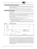
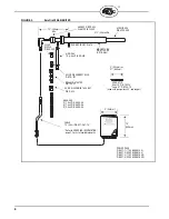
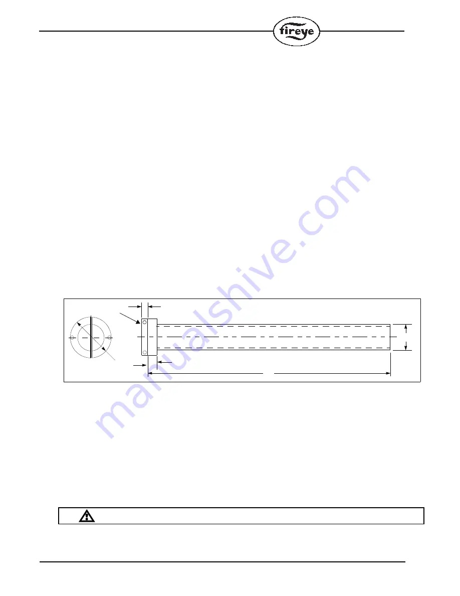
FIGURE 4.
Typical SureFire 20 Mounting Tube
Fuel and Air Piping
1.
To prevent contamination of the igniter during commissioning, ensure that all fuel and air piping
and flexible hoses have been blown free of any debris or moisture. During installation, tapping
off the gas header from the top or side also prevents contamination.
NOTE: Equal gas flow and pressure distribution to each igniter are important for reliable and
efficient operation of the igniter. Care should be exercised in the design, especially on multiple
igniter/burner furnaces, to achieve even distribution under all flow conditions. Good engineer-
ing practice recommends limiting the line velocities of gas fuel to a maximum of 9000 ft./min.
2.
Install gas pressure regulators with the required turndown capacity and response time capability,
in the gas headers to ensure that the specified gas pressure is maintained at the igniter.
CAUTION: Design and install flexible hoses to allow for maximum boiler expansion.
3.
Connect the flexible gas hose from the supply piping to the corresponding connection on the
SureFire™ igniter. Install the flexible hose with all of the bends in one plane. The hose cannot
withstand twisting or kinking; if necessary, install an additional union.
74.7 DIA
12.7
19.1
1503
(.75)
(.50)
54.1
(2.13)
(2.94)
DIMENSIONS IN MM (INCHES)
L
MATERIAL: CARBON STEEL, RED PRIMER PAINTED
CLAMPING COLLAR
Summary of Contents for SureFire 20
Page 15: ...15 ...


