4
SUREFIRE IGNITER SPECIFICATION PROCEDURE
A complete Fireye gas igniter assembly will consist of at least three part numbers, each ordered sep-
arately. These include the SureFire 20 Gas Igniter, the High Energy Igniter (HEI) power pack, and
the HEI interconnecting cable.
Optional accessories, ordered separately, include the Mount Tube, Air Hose, and Gas Hose.
SUREFIRE MODEL 20 GAS IGNITER
The SureFire gas Igniter is sized to fire natural gas with an output of 1.0MBTU/hr at a pressure of 10
psig (690 millibars).
Each igniter comes with a 1.88" (48 mm) OD guide tube assembly, HEI spark rod, 1/2" NPT gas
inlet connection, 3/4" NPT cooling/combustion air inlet connection. Air flow of 12 SCFM @ 3"
W.C. above Windbox pressure is required through the guide tube at all times
The HEI cable and HEI power pack must be selected from the HEI component list to provide a com-
plete working assembly.
Mounting the igniter to the burner front plate can be done several different ways;
1.
The guide tube can be welded to the burner front plate.
2.
A mount plate fabricated on site, can be welded to the guide tube and that assembly can be
welded or bolted to the burner front plate.
3.
A mount tube with packing gland can be welded to the burner front plate. Then the igniter is
inserted into the mount tube and allowing the packing gland to be tightened around the guide
tube.
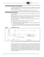
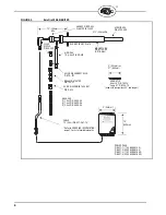
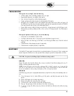
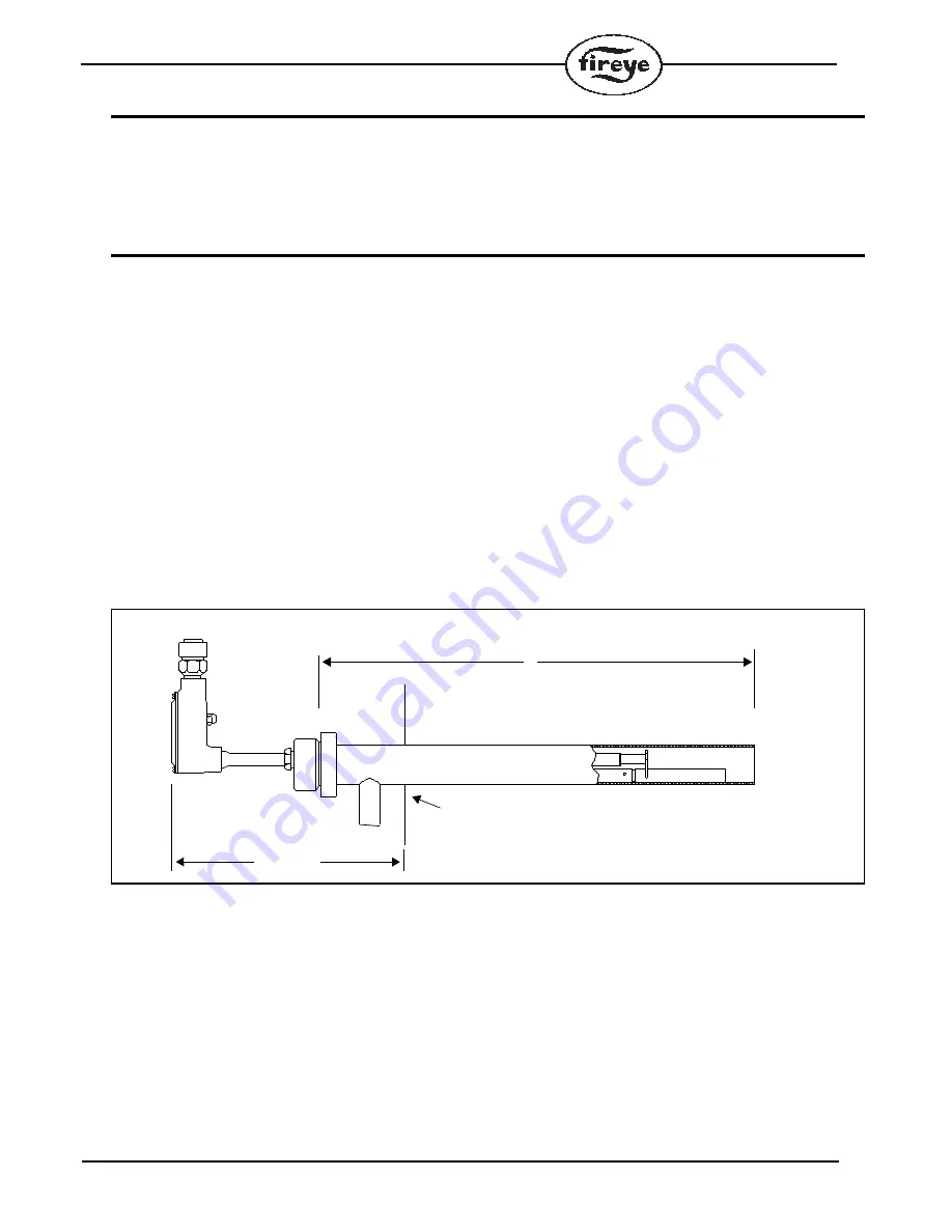
FIGURE 2.
SureFire Model 20 Gas Igniter
Length “L” is the distance from the firing tip of the igniter back to the break point of the rear flange.
In selecting the length of the SureFire Gas Igniter, there are two dimensions that make up the total
length of the igniter. One is the distance from the firing tip back to the burner frontplate, and the sec-
ond is the distance from the burner front plate back to the rear flange. The total of these two dis-
tances will equal dimension “L” of the igniter. The first dimension is dependent on the burner size
and must be measured or taken from a burner dimensional drawing. As a general rule the firing tip of
a gas igniter can be located 6" (153mm) behind the oil gun. If a bluff body diffuser is used to stabi-
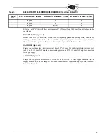
lize the flame, the igniter must be mounted flush with the diffuser/stabilizer. Refer to the chart below
for the igniter set back dimensions. This igniter can be used in a Class 1, 2 or 3 in either a continuous
or intermittent application.
14” (350)
Min
DIMENSIONS in (mm)
L
FRONT PLATE
Summary of Contents for SureFire 20
Page 15: ...15 ...


