background image

9

®

SAFETY

Safety is the responsibility of each individual who installs, operates or maintains Fireye equipment.
Fireye includes personnel safety as a basic design element of the SureFire igniter.

Observe the following safety instructions prior to performing installation, operation, or maintenance:

WARNING: Hazardous voltage is present and serious injury can occur. See HEI bulletin SF-1. 

1.

Use this equipment only for its intended purpose.

2.

Follow only the installation, operation, and maintenance procedures discussed in this publica-
tion and on appropriate drawings.

3.

Ensure that all electrical apparatus used to perform work on this equipment is in good working
order and has been calibrated correctly.

4.

Do not lift or disconnect grounding cables/wires while equipment is energized.

5.

Do not perform modifications on this equipment.

6.

Before opening the HEI power unit's hinged cover, disconnect the electrical supply from the
box. Allow at least 2 minutes for the capacitor to discharge. Exercise extreme care when the
power unit cover is open. Refer to the HEI Service Manual for complete safety instructions for
HEI equipment.

7.

Ensure that no voltage is present prior to disconnecting terminations.

8.

Adhere to safety-related information on all drawings.

9.

Close the manual fuel shutoff valves before performing maintenance or troubleshooting proce-
dures.

10.

Test all fuel gas pipe connections for leaks.

11.

The HEI power pack enclosure and the igniter guide tube should be grounded. (See HEI bulletin
SF-1 for details.)

12.

When removing the igniter assembly from an operating furnace, wear protective clothing and
insulated gloves. While observing the igniter flame through an open observation port, wear a
face shield and protective clothing.

WARNING: Only knowledgeable and qualified technicians should be allowed access to this
system or to its components. The installation, maintenance, and operation of electronic equip-
ment entails several elements of danger. Carelessness can result in serious injury or death
from electrical shock, falls, or improper use of tools and test equipment.

INSTALLATION

A detailed description of the SureFire™ gas igniter installation follows. For job-specific installation
instructions, refer to the appropriate arrangement and installation drawings. 

During installation, protect terminal boxes, spark rods, surfaces, round tubes, or any other protruding
devices from accidental bumps or bending forces.

The design of the SureFire™ gas igniter allows the user to weld the guide tube directly to the burner
front plate, if desired. With this configuration, no mount tube is required. When welding the guide
tube to the burner front plate, position the SureFire™ tip 3 inches behind the burner fuel vertical
plane, as a general rule. The igniter guide tube is stainless steel; therefore, a stainless weld procedure
is required.

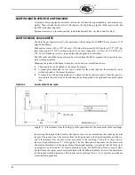
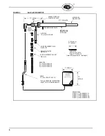
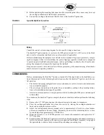
Optional Mounting Tube

The mounting tube (Figure 4) is affixed permanently to the burner front plate and supports the igniter
assembly. If a suitable mounting tube is not available, one must be installed. However, many retrofit
installations may have a suitable mounting tube. The inside diameter of an existing mounting tube
must provide adequate sliding clearance from the outside diameter of the guide tube, in order to pre-
vent binding of the igniter during installation. In cases where a mounting tube must be installed, per-
form the following steps.

Summary of Contents for SureFire 20

Page 1: ...e not intended for warm up or support These igniters are provided with a durable High Energy Igniter HEI for repeatable light off Refer to the HEI bulletin for detailed HEI information In most applications the self contained SureFire gas igniters are mounted in a burner through a mounting tube The major components of the SureFire gas igniters are the guide tube assembly and the HEI Figure 1 shows ...

Page 2: ...ntinued 3 SPECIFICATIONS 3 SUREFIRE IGNITER SPECIFICATION PROCEDURE 4 SUREFIRE MODEL 20 GAS IGNITER 4 SUREFIRE 20 ORDERING INFORMATION 7 SAFETY 9 INSTALLATION 9 COMMISSIONING 11 OPERATION 12 TROUBLESHOOTING 13 MAINTENANCE 13 STORAGE 14 SUREFIRE MODEL 20 OUTPUT CURVE 14 ...

Page 3: ... place by a split clamping ring squeeze collar which is bolted to the mounting tube The squeeze collar also acts as a packing gland follower High Energy Igniter HEI The HEI spark rod provides a 12 joule spark which ignites the gas air mixture The HEI consists of a fouling resistant surface gap spark tip connected to a positioning rod power unit and cable See HEI bulletin for details View Port An i...

Page 4: ...and that assembly can be welded or bolted to the burner front plate 3 A mount tube with packing gland can be welded to the burner front plate Then the igniter is inserted into the mount tube and allowing the packing gland to be tightened around the guide tube FIGURE 2 SureFire Model 20 Gas Igniter Length L is the distance from the firing tip of the igniter back to the break point of the rear flang...

Page 5: ...he complete igniter from the burner front GAS HOSE Optional Fireye can provide a flexible stainless steel hose 0 5 13 mm ID with single braid stainless steel jacket a 0 5 13 mm NPT nipple connection to igniter and a 0 75 19 mm NPT nipple connection to the gas supply AIR HOSE Optional Fireye can also provide a reinforced 1 ID rubber air hose with a 1 NPT nipple connection to air supply at one end a...

Page 6: ...ONNECT SOCKET GAS HOSE CABLE 15 4 5m P N SF1 CA1 15 P N 9 438 P N 148 21 4 1 2m P N GH20 04 6 1 8m P N GH20 06 8 2 4m P N GH20 08 SPARK TIP Short 8 P N Long 27 P N 145 19 8 203mm or 27 685mm 8 203mm 10 250mm POWER PACK P N SF1 1 110 VAC NEMA 4 P N SF1 2 220 VAC NEMA 4 P N SF1 3 110 VAC NEMA 4X P N SF1 4 220 VAC NEMA 4X GASKET P N 29 403 145 18 used with gas igniters 38 and longer Refer to ORDERING...

Page 7: ...niter lengths 062 through 070 MT20 062 Mount Tube 62 long igniter lengths 072 through 080 MT20 072 Mount Tube 72 long igniter lengths 082 through 090 MT20 082 Mount Tube 82 long igniter lengths 092 through 100 MT20 092 Mount Tube 92 long igniter lengths 102 through 110 MT20 102 Mount Tube 102 long igniter lengths 112 through 120 MT20 112 Mount Tube 112 long igniter lengths 122 through 130 MT20 122...

Page 8: ... longer PART NUMBER DESCRIPTION SF1 1 SureFire HEI Power Pack 110 vac NEMA 4 painted steel SF1 2 SureFire HEI Power Pack 220 vac NEMA 4 painted steel SF1 3 SureFire HEI Power Pack 110 vac NEMA 4X stainless steel SF1 4 SureFire HEI Power Pack 220 vac NEMA 4X stainless steel PART NUMBER DESCRIPTION SF1 CA1 06 SureFire HEI interconnecting cable with connectors 6 feet long SF1 CA1 09 SureFire HEI inte...

Page 9: ...ctive clothing and insulated gloves While observing the igniter flame through an open observation port wear a face shield and protective clothing WARNING Only knowledgeable and qualified technicians should be allowed access to this system or to its components The installation maintenance and operation of electronic equip ment entails several elements of danger Carelessness can result in serious in...

Page 10: ...tube to assist with sliding it through the squeeze collar 3 POSITION THE SUREFIRE igniter assembly to the depth shown on the burner installation draw ing During replacement applications insert the furnace end of the SureFire guide tube assembly to the same location as the previous igniter As a general rule locate the SureFire tip 3 inches behind the burner fuel nozzle vertical plane FIGURE 4 Typic...

Page 11: ... ini tial operation The fuel and air piping configuration is correct and dampers valves strainers and instrumenta tion are installed properly The air and gas connections to the guide tube are installed according to the preceding instruc tions or the installation drawings if provided All electrical components are wired properly and tested including the HEI power unit and spark rod assembly To commi...

Page 12: ...repare the igniter gas supply and header system to allow pressure to the individual igniter block valves 4 Set the igniter fuel regulator to the specified pressure 5 Initiate an igniter start The following sequence of events occurs as the SureFire igniter goes into service The HEI is energized and starts to spark The gas double block valve opens and the vent valve closes admitting fuel to the igni...

Page 13: ...lame detector is sighted properly if applicable MAINTENANCE The SureFire components discussed below require maintenance Proper care of these components ensures long and reliable service On a periodic basis complete preventive maintenance activities CAUTION Use protective clothing and gloves if furnace is in operation Guide Tube Inspect the guide tube from the furnace side or remove internals from ...

Page 14: ... ensure that igniter is receiving adequate air flow STORAGE Store the SureFire igniter in a clean dry atmosphere When possible store the assembly in its orig inal shipping container until used If the SureFire igniter is removed from its shipping container store it in a horizontal position supported at both ends of the guide tube Protect both guide tube ends from damage due to inadvertent bumps or ...

Page 15: ...15 ...

Page 16: ...cells which is found defective in material or workmanship or which otherwise fails to conform to the description of the product on the face of its sales order THE FOREGOING IS IN LIEU OF ALL OTHER WARRANTIES AND FIREYE MAKES NO WARRANTY OF MERCHANTABILITY OR ANY OTHER WARRANTY EXPRESS OR IMPLIED Except as specifically stated in these general terms and conditions of sale remedies with respect to an...

Reviews: