background image


© 2021 Carrier 


10.1 INSPECTION AND MAINTENANCE 

SP-32-NG/PG-FD 

pilot because of its simple design does not require complicated maintenance procedures. 

Checking and cleaning of gas tube and orifice-stabilizer assembly: 

a)


Close the manual gas valve and disconnect the pilot gas line. 

b)


Disconnect the ignition rod electric supply cable. 

c)


Unscrew the locking screw and the mounting ring. 

d)


Carefully slide out the gas part assembly from the air tube. 

e)


Check the ignition rod at least every 12 months. For checking and standard service do not remove the rod 
from the gas part. Follow the igniter User’s Manual. 
Pull out the electrical igniter only if it is absolutely necessary e.g. when rod is worn or damaged and has to  
be repaired or replaced. Before that, loose the ignition rod holding gland and then follow p. 7.2. 
Unscrew the rod tip before pulling out rod from the gas part and holding gland for easier slide without any 
jamming.  

f)


Check and clean the bleed orifice and main nozzle. For cleaning use a soft copper wire. 

g)


To remove heavy dirt use a soft wire brush e.g. copper wire brush. 

h)


Blow compressed air through the whole gas part assembly. 

i)


To check the air tube condition loosen the mounting tube clamp assembly screws and pull out air tube. 
Check for overheating traces and clean it. 

j)


Assemble all the elements back to obtain the original configuration. 

Checking of ignition device: 

k)


Check the complete ignition device at least every 12 months. Follow instructions in its User's Manual. 

10.2 TROUBLESHOOTING 

If the gas pilot does not operate correctly check the following: 

a)


All manual gas valves on gas supply line were open and there is gas available. 

b)


All valves in the supply line are functioning properly. 

c)


The preset gas pressure is correct. 

d)


The correct pilot air pressure is maintained. 

e)


Gas and air supply lines are clear - check strainers. 

f)


Bleed orifice and the main orifice in orifice-stabilizer assembly are clear. 

g)


Electric ignition device is working correctly and its rod is correctly positioned in gas part assembly. If it is 
not working properly - follow the ignition device manual. 

h)


The power parameters for ignition device are correct. 

If the gas lights but the flame is unstable, or goes out when main burner goes into operation, check that: 

i)


The gas pressure does not drop during pilot light-off (trial for ignition). 

j)


The air pressure is always at the correct level. 

k)


The air from the main burner does not blow out the pilot flame or does not move it out of the field of view 
of the flame scanner (if applied). 

l)


Flame safeguard system works correctly and the flame is not obscured. 

Improper operation of the whole installation requires the detailed checking of the power line and all components, 
including any temporary use of override switches or jumpers. 
Be aware of all connections to be later restored to normal state, to allow safe operation. 

11. 

SPARE PARTS, WARRANTY CONDITIONS 

11.1 For start-up and warranty period it’s recommended to order following spare parts in quantity as below: 

– 

a set of loose parts used on both sizes on pilots: 

SP-32 

and 

SP-48 

(see Fig. 5)    - one for 4 pilots, 

– 

complete orifice-stabilizer assembly for 

SP-32-FD 

pilot, including: 

- one for 4 pilots. 

nipple with bleed and main orifice, mounting bracket, stabilizer 

Summary of Contents for SureFire II SP32-NG-FD

Page 1: ...or LPG gas is SP 48 PG FD xxx where xxx is the insertion length L from 0 5 to 3 0 metres see Appendix 1 the pilot capacity vs gas pressure graphs for Natural gas and Propane For other Fuel gas types...

Page 2: ...and should be ordered separately SP 32 FD pilot principle of use gas is supplied through the inlet 1 2 BSP to the gas head and to the gas tube and orifice stabilizer assembly Gas exits the main nozzle...

Page 3: ...n left to be welded to the burner plate Pilot fixing inside the mounting tube as in p 7 1 There are two lengths A available 150 and 600 mm FIGURE 3 Gas pilot type SP 32 NG PG FD with examples of elect...

Page 4: ...2 BSP inner thread Operating temperature max continuous 300 C orifice stabilizer end of gas and air tube 500 C Igniter rod reference length range L 0 5 3 0 m longer upon request Pilot weight P N SP 3...

Page 5: ...S IN OPERATION ALWAYS KEEP THE PROPER AIRFLOW OF PILOT COMBUSTION COOLING AIR 7 1 MOUNTING TUBE The mounting tube if used should be attached to the burner plate using bolts or welding see Fig 2 If it...

Page 6: ...ign of the main burner If an existing pilot has to be replaced the insertion length and pilot tip position should be the same In case of any doubts the position of the pilot should be consulted with t...

Page 7: ...the air tube may start to glow it starts to glow at 400 500 C as the main flame burns inside the igniter Further opening of the air valve should stabilize the flame outside the air tube This will sto...

Page 8: ...absence of the flame after trial for ignition the valves are closed and electrical igniter is switched off i Eventual repeating of trial for ignition sequence depends on the application Details of seq...

Page 9: ...ilot does not operate correctly check the following a All manual gas valves on gas supply line were open and there is gas available b All valves in the supply line are functioning properly c The prese...

Page 10: ...allation operation maintenance of igniter contrary to the instructions in the user manual unauthorized igniter modifications or repairs made by unauthorized personnel use of components or spare parts...

Page 11: ...Natural Gas or Propane Gas Forced Draught 3 0 m insertion length The Table 2 below shows Part Numbers of gas igniter mounting tubes and spare parts Table 2 SureFire II Pilot Mounting Tubes Spare Part...

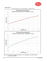
Page 12: ...12 2021 Carrier APPENDIX No 1 The Pilot capacity vs gas pressure graphs standard version Remark The real measured capacity may differ by 5 depending on a particular pilot and measurement conditions...

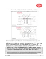
Page 13: ...ndustrial heaters shows position of SP 32 and SP 48 Gas Igniter operating as a continuous pilot on a sample main burner with gas spuds and central oil or gas gun vertical mounting The pilot air tube t...

Page 14: ...biogas and especially refinery gas Refinery Off Gas needs additional engineering and testing because their gas compositions and calorific values are different than these of NG PG and LPG taken for gas...

Page 15: ...35 315 cubic foot ft3 Air flow rate 1 cubic meter hour m3 h x 0 589 standard cubic foot min SCFM Weight 1 kilogram kg x 2 2046 pound lb Pressure 1 kilopascal kPa x 6 895 pound square inch gauge psig...

Page 16: ...ls which is found defective in material or workmanship or which otherwise fails to conform to the description of the product on the face of its sales order THE FOREGOING IS IN LIEU OF ALL OTHER WARRAN...

Reviews: