background image

BP-325 System manual version 1.1 


14

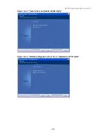
Step 5. 

Click “Next” to continue   


Step 6. 

Click “Finish” to complete setup 


Summary of Contents for BP-325

Page 1: ...User s Manual BP 325 Version 1 1 Copyright 2011 All rights reserved All other brand names are registered trademarks of their respective owners ...

Page 2: ...mation provided in this manual is intended to be accurate and reliable However Firich Enterprise Co Ltd assumes no responsibility for its use nor for any infringements upon the rights of third parties which may result from its use The material in this document is for product information only and is subject to change without notice While reasonable efforts have been made in the preparation of this ...

Page 3: ... on it Do not place anything over the power cord 10 All cautions and warnings on the equipment should be noted 11 If the equipment is not used for a long time disconnect it from the power source to avoid damage by transient over voltage 12 Never pour any liquid into an opening This could cause fire or electrical shock 13 Never open the equipment For safety reasons only qualified service personnel ...

Page 4: ...allation and Setup 9 Driver Download from FEC Website Model 9 Intel ATOM D525 Chipset Installation Utilities for Windows XP 10 VGA Driver Installation 12 LAN Driver Installation 15 Audio Driver Installation 16 Wireless LAN optional Driver Installation 17 Chapter4 20 Specifications 20 BP 325 System Specifications 20 I O Pin Definition 21 Chapter5 25 Troubleshooting 25 Display Shows No Signal Before...

Page 5: ...and use BP 325 Chapter 1 Provides an introduction to BP 325 and this manual Chapter 2 Provides all necessary information for all hardware setup Chapter 3 Provides the necessary information for installing for chipset and its accessories Chapter 4 Lists all BP 325 specifications Chapter 5 Troubleshooting of BP 325 ...

Page 6: ...n with feature of easy maintenance and abundant I O access make it a decent choice for POS application System Equipped with Intel D525 and ICH8M chipset Housing BP 325 is made with strong metal housing suitable Extensibility Low profile design with abundant I O access BP 325 is ideal for connecting a variety of system devices DC 12V out supported For Display Abundant I O allowed the box for differ...

Page 7: ...BP 325 System manual version 1 1 2 BP 325 Dimensions ...

Page 8: ...dard USB connector for external device LPT Port D Sub 25 Connector The parallel port LPT1 can be used to connect parallel devices such as a printer K B Mouse PS 2 Keyboard Connector The port is for connecting an external keyboard or mouse Cash Drawer RJ11 Connector Cash Drawer Connector 12V supported COM1 COM2 COM3 COM5 COM6 D Sub 9 Pin Connector The serial ports can be used to connect serial devi...

Page 9: ...BP 325 System manual version 1 1 4 Packing List The following items are standard with BP 325 AC Power Cord x 1 12V DC 60W Power Adaptor ...

Page 10: ...pre requested BP 325 2 5 HDD or other storage disassembly process 1 Turn off the system and remove power cable from main unit 2 Unlock the screw and open the HDD door Do not remove the top cover until you have verified that no power is supplied to the system The system must be switched off and the power cord must be unplugged Every time you service the system you should be aware of this ...

Page 11: ...manual version 1 1 6 3 Take off the cover and beware of the cables 4 Take off the SATA cable 5 Open the tray of HDD bracket 6 Change the HDD and lock back to the tray 7 Put it back to main unit and fix with the screw ...

Page 12: ...325 System manual version 1 1 7 Memory DDRIII RAM Installation 1 Remove two screws on the back cover and take off it 2 Remove four screws on the M B and pull it up 3 Access to RAM slot and restore the unit ...

Page 13: ...o cash drawer port Note If the cash drawer cannot be detected by the system please refer to troubleshooting Up to two cash drawers may be driven from this port Driving voltage of the solenoid is DC 12V I O port 284 is used for drawer operation A test program is supplied for Linux and Windows source code of which is available on request by software developers Value Description 0x284 Output address ...

Page 14: ...del BP325 comes with a variety of drivers for different operating systems A Please go to FEC website and download BP 325 driver B The installation sequence Chipset Driver VGA Driver LAN Driver Audio Driver Other Driver optional C Then you can start to install Please follow this installation sequence accordingly ...

Page 15: ... version 1 1 10 Intel ATOM D525 Chipset Installation Utilities for Windows XP Step 1 Please double confirm the Intel chipset driver from website Step 2 Click Next Step 3 Read the License Agreement and click Yes to continue ...

Page 16: ...BP 325 System manual version 1 1 11 Step 4 Click Next to continue Step 5 Click Next to continue ...

Page 17: ...BP 325 System manual version 1 1 12 Step 6 Click Finish to complete setup VGA Driver Installation Step 1 Please double confirm the VGA driver from website Step 2 Click Next ...

Page 18: ...BP 325 System manual version 1 1 13 Step 3 Read the License Agreement and click Yes to continue Step 4 Click Next to continue ...

Page 19: ...BP 325 System manual version 1 1 14 Step 5 Click Next to continue Step 6 Click Finish to complete setup ...

Page 20: ...BP 325 System manual version 1 1 15 LAN Driver Installation Step 1 Please double confirm the LAN driver from website Step 2 Click Next Step 3 Click Next to continue ...

Page 21: ...BP 325 System manual version 1 1 16 Step 4 Click Finish to complete setup Audio Driver Installation Step 1 Please double confirm the Audio driver from website Step 2 Click Next ...

Page 22: ...BP 325 System manual version 1 1 17 Step 3 Click Finish to complete setup Wireless LAN optional Driver Installation Step 1 Please double confirm the wireless LAN driver from website Step 2 Click Next ...

Page 23: ...BP 325 System manual version 1 1 18 Step3 Select Install driver and Ralink WLAN Utility Step4 Select Ralink Configuration Tool Select Optimize for WiFi mode ...

Page 24: ...BP 325 System manual version 1 1 19 Step5 Select Install Step6 Click Finish ...

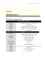
Page 25: ...io Realtek ALC269 Connectors Serial Port 5 x COM ports DB 9 male with 5 12v DC output 1 x COM port RJ 45 for 12V Customer display Parallel Port 1 x Parallel port DB25 female USB Port 1 x USB 2 0 type A front panel 4 x USB 2 0 type A rear panel 3 x On board pin header Cash drawer Port 1 x 12V RJ11 Keyboard Mouse Port 1 x PS 2 LAN Port 1 x RJ45 10 100 1000 Base T Audio Port 1 x Line out 1 x Mic in i...

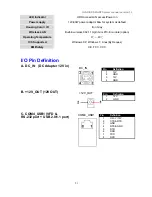
Page 26: ...2 11 b g n mini PIC E module option Operating Temperature 0 40 O S Supported Windows XP Windows 7 Linux By Reques EMI Safety CE FCC CCC I O Pin Definition A DC_IN DC Adapter 12V in B 12V_OUT 12V OUT C COM4_USB1 VFD RS 232 port USB 2 0 1 1 port Pin Definition 1 12V 2 GND 3 12V 4 GND Pin Definition 1 12V 2 GND COM4_USB1 Pin Definition 1 RI 5V 12V 2 CTS RTS 3 GND 4 RTS GND 5 DTR 6 DSR 7 TXD 8 RXD 12V...

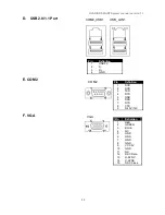
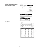
Page 27: ...A Pin Definition 1 RED 2 GREEN 3 BLUE 4 NC 5 GND 6 GND 7 GND 8 GND 9 VCC 5V 10 GND 11 NC 12 DDC Data 13 H SYNC 14 V SYNC 15 DDC Clock COM4_USB1 USB_LAN1 Pin Definition 1 USB 5V 2 D 3 D 4 GND COM2 Pin Definition 1 DCD 2 RXD 3 TXD 4 DTR 5 GND 6 DSR 7 RTS 8 CTS 9 RI 5V 12V VGA ...

Page 28: ... 7 Data 3 8 Data 3 Connection Speed LED State Description Orange Speed 1 Gbps Green Speed 1 00 Mbps Activity LED State Description On Transmitting Off Not Transmitting LPT Pin Definition Pin Definition 1 STB 14 AFD 2 PD0 15 ERR 3 PD1 16 INIT 4 PD2 17 SLIN 5 PD3 18 GND 6 PD4 19 GND 7 PD5 20 GND 8 PD6 21 GND 9 PD7 22 GND 10 ACK 23 GND 11 BUSY 24 GND 12 PE 25 GND 13 SLCT ...

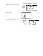
Page 29: ... Port K AUDIO_JACK Audio Line Out Pin Definition 1 Keyboard Data 2 Mouse Data 3 GND 4 Mouse Clock 5 5V 6 Keyboard Clock Pin Definition 1 GND 2 GPIO 0 3 CASH Drawer Switch 4 12V 5 GPIO 1 6 GND RJ11 Pin Definition 1 GND 2 Line Out L 3 AUDIO_JD 4 ACZ_DET 5 Line Out R Audio Jack ...

Page 30: ...y display As a result the monitor VGA connected device will then be defined as the 2nd display and No Signal will show on the screen To switch the monitor back to the primary display please connect a keyboard to the system and press Ctrl Alt F1 simultaneously Cannot Detect HDD A SATA cable is not connected properly to main board B HDD power cable is not connected properly to the main board or it c...

Reviews: