background image

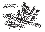
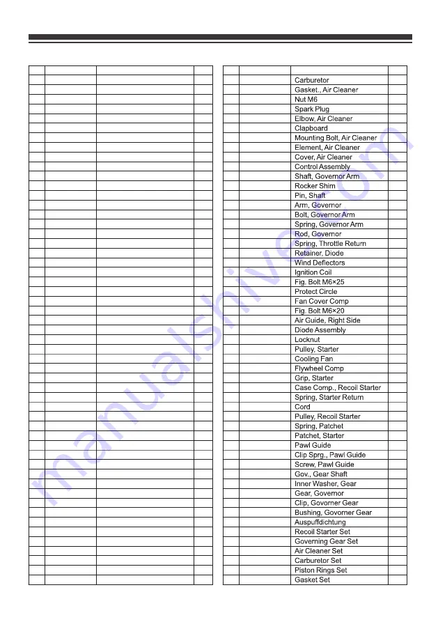
FIRMAN 208cc Engine Parts List

336723500
336723501
336723502
336723503
336723504
336723505
336723506
336723507
336723508
336723509
336723510
336723511
336723512
336723513
336723514
336723515
336723516
336723517
336723518
336723519
336723520
336723521
336723522
336723523
336723524
336723525
336723526
336723527
336723528
336723529
336723530
336723531
336723532
336723533
336723534
336723535
336723536
336723537
336723538
336723539
336723540
336723541
336723542
336723543
336723544
336723545
336723546
336723547
336723548
336723549
336723550
336723551
336723552

1
2
3
4
5
6
7
8
9

10
11
12
13
14
15
16
17
18
19
20
21
22
23
24
25
26
27
28
29
30
31
32
33
34
35
36
37
38
39
40
41
42
43
44
45
46
47
48
49
50
51
52
53

NO. Part Number

Description

Qty.

1
2
1
8
1
2
1
1
1
1
1
1
1
2
6
1
2
1
1
1
1
1
3
1
1
1
7
4
2
2
1
2
1
1
1
2
2
2
1
2
1
1
1
2
2
2
2
2
1
2
1
1
1

336723553
336723554
336723555
336723556
336723557
336723558
336723559
336723560
336723561
336723562
336723563
336723564
336723565
336723566
336723567
336723568
336723569
336723570
336723571
336723572
336723573
336723574
336723575
336723576
336723577
336723578
336723579
336723580
336723581
336723582
336723583
336723584
336723585
336723586
336723587
336723588
336723589
336723590
336723591
336723592
336723593
336723594
336723595
336723596
336723597
336723598
336713532
336423500
336423501
336423502
336423503
336423504
336423505

54
55
56
57
58
59
60
61
62
63
64
65
66
67
68
69
70
71
72
73
74
75
76
77
78
79
80
81
82
83
84
85
86
87
88
89
90
91
92
93
94
95
96
97
98
99

100
101
102
103
104
105
106

NO. Part Number

Description

Qty.

1
1
3
1
1
1
4
1
1
1
1
1
1
1
1
1
1
1
1
1
1
2
1
1
1
1
1
1
1
1
1
1
1
1
1
1
2
2
1
1
1
1
1
1
1
1
1
1
1
1
1
1
1

Crankcase Subassembly.
Locating Pins
Sensor, Engine Oil
Flg. Bolt M6×12
Camshaft Assy.
Bearing
Gear, Crankshaft
Woodruff Key
Crankshaft
Gear, Drive
Gasket, Crankcase
Oil Dipstick Assy
Cover, Crankcase
Seal, Oil
Flg. Bolt M8×32
Rod, Connecting
Clip, Piston Pin
Pin, Piston
Piston
Ring Set, Oil
Ring, The Second 
Ring, The First
Flg. Bolt M6×8
Air Guide Lower

Flg. Bolt M6×15
Flg. Bolt M8×55
Nut, Valve Lock
Nut Valve Adjusting
Breather Tube
Rocker, Valve
Rotator, Valve
Retainer, Intake Valve
Retainer, Exhaust Valve
Spring, Valve
Oil Seal, Valve
Bolt, Valve Adjusting

Exhaust Valves Stud Bolt

Valve, Intake
Valve, Exhaust
Push Rod
Tappet, Valve
Washer, Drain Bolt
Bolt, Drain Plug
Locating Pins
Gasket, Cylinder Head
Stud, Intake
Gasket, Inlet
Plate, Carburetor Insulator
Gasket, Carburetor

Cover Subassembly, Cylinder Head

Gasket, Cylinder Head Cover

Plate Subassembly, Lifter Stopper

Head Subassembly, Cylinder

Learn more about generators we have.

Summary of Contents for P03501

Page 1: ...operating equipment Ensure engine is stopped and level before performing any maintenance or service IMPORTANT Record product information to reference when ordering parts or obtaining warranty coverag...

Page 2: ...Table of Contents Connecting to a Building s Electrical Trouble Shooting 24 Parts Diagram and Parts List 25 Generator Parts Diagram 25 Engine Parts Diagram 26 Parts List 27 Service Information 29 22...

Page 3: ...e that the procedure work method or operating technique that you choose does not render the generator unsafe DANGER WARNING CAUTION DANGER indicates a potentially hazardous situation which if not avoi...

Page 4: ...SAFETY PRECAUTIONS WARNING POISONOUS GAS HAZARD WARNING WARNING...

Page 5: ...ONLY use outside and downwind far away from windows doors and vents Direct exhaust away from occupied spaces INCORRECT USAGE Do not operate in any of the following locations Near any door window or v...

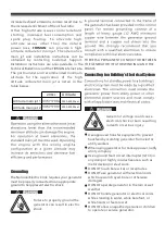
Page 6: ...could cause burns fire or explosion resulting in death or serious injury and or property damage WHEN ADDING OR DRAINING FUEL Turn generator engine OFF and let it cool at least 2 minutes before removi...

Page 7: ...et weather DO NOT handle generator or electrical cords while standing in water while barefoot or while hands or feet are wet DO NOT allow unqualified persons or children to operate or service generato...

Page 8: ...s or medical appliances Inform your electricity provider immediately if you or anyone in your household depends on electrical equipment to live Inform your electrical provider immediately if a loss of...

Page 9: ...y Refer to the following instructions and pictures to remove the attached engine support brackets red under the engine 3 You may discard these brackets as they are no longer required for normal operat...

Page 10: ...erator requires some assembly prior to usage Install the Wheel Kit F E G H K 1 Before adding wheels tip the generator on its side 2 Slide the axle pin A through the wheel B 3 Slide the axle pin A thro...

Page 11: ...r 5 Fuel Valve 6 Air Filter 7 208cc FIRMAN OHV Engine 8 Recoil Starter 9 Bottle Opener 10 8 0 Flat Free Wheel 11 Oil Filler Cap 12 Outlet Cover 13 Control Panel 14 Handle We are always working to impr...

Page 12: ...30A RV NEMA TT 30R Total power drawn from all receptacles must not exceed the name plate rating NOTE 8 Outlet Cover Protect the receptacles from dust and debris 8 A Digital display B AC voltage indica...

Page 13: ...tive Gasoline Recoil 5 0 Gallon 20 3 oz 0 6L Counter Clockwise Facing P T O Float Brushed Polyurethane Type Yes 4450 FIRMAN Rated Fequency 60Hz Oil Type See Add Engine Oil Section Spark Plug AN IMPORT...

Page 14: ...the sensor will activate a warning device or stop the engine If generator shuts off and the oil level is within specifications check to see if generator is sitting at an angle that forces oil to shif...

Page 15: ...uel to fuel tank Be careful not to fill above the red fuel level indicator This allows adequate space for fuel expansion 3 Install fuel cap and let any spilled fuel evaporate before starting engine or...

Page 16: ...erate generator in the rain or wet weather DO NOT handle generator or electrical cords while standing in water while barefoot or while hands or feet are wet DO NOT allow unqualified persons or childre...

Page 17: ...protected from the weather Keep exhaust pipe clear of foreign objects Keep generator away from open flame Keep generator on a stable and level surface WARNING Surge Protection Voltage fluctuation may...

Page 18: ...tion 9 Allow generator to run at no load for few minutes upon each initial start up to permit engine and generator to stablize WARNING When starting engine pull cord slowly until resistance is felt an...

Page 19: ...ine speed adjusted at the factory for correct output Readjusting will void warranty CAUTION When applying a load do not exceed the maximum wattage rating of the generator when using one or more recept...

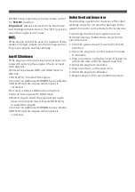
Page 20: ...below LOW mark on dipstick 1 Add oil to bring level to HIGH mark 2 Restart engine and if the engine stops again a low oil condition may still exist DO NOT try to restart the engine 3 Contact an Author...

Page 21: ...ndations Regular maintenance will improve the performance and extend the life of the generator See any authorized dealer for service The generator s warranty does not cover items that have been subjec...

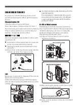
Page 22: ...ain laboratory animals Thoroughly wash exposed areas with soap and water a Drain oil by removing the drain plug and the oil filler cap while the engine is warm Change engine oil every 100 hours for a...

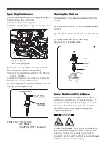
Page 23: ...ainer cup with gasoline c Tightly fasten the cup to main body making sure to avoid fuel leak SCREEN O ring CUP BODY b Remove spark plug using provided wrench Inspect spark plug for damage and clean wi...

Page 24: ...rator Water can enter the generator through the cooling slots and damage the generator windings Use a damp cloth to clean exterior surfaces of the generator Use a soft bristle brush to remove dirt and...

Page 25: ...out one teaspoon of engine oil through the spark plug hole then pull the recoil starter several times to distribute the oil for lubricating the cylinder Reattach the spark plug Pull recoil slowly unti...

Page 26: ...as lost compression 1 Set engine switch to ON l position 2 Move fuel shutoff lever to ON l position 3 Fill crankcase to proper level or place generator on level surface 4 Clean or replace air cleaner...

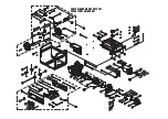
Page 27: ...PARTS DIAGRAM AND PARTS LIST P03501 PARTS DIAGRAM...

Page 28: ...FIRMAN 208cc Engine Parts Diagram...

Page 29: ...336413502 336413503 336413508 336413509 Fuel Valve Guard Muff Frame Axle Pin Wheel Cotter Pin Rubber Support Nut M8 Bolt M8 16 Support Leg Bolt M6 25 IsolatorA Isolator B Grommet Screw M5 14 Control...

Page 30: ...587 336723588 336723589 336723590 336723591 336723592 336723593 336723594 336723595 336723596 336723597 336723598 336713532 336423500 336423501 336423502 336423503 336423504 336423505 54 55 56 57 58 5...

Reviews: