FB100AS-F User Guide
Version 1.0
5
Interface
Page 11 / 30
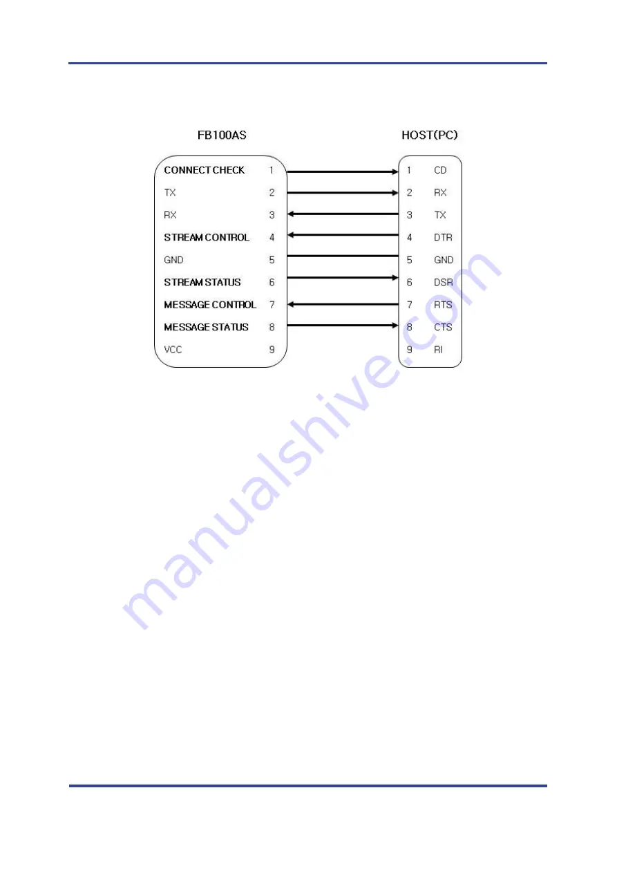
5.2.3 Connection Diagram with 1:N Function
<Figure 5-4 Connection Diagram with 1:N Function>
Note
:
If Flow Control is not required, communication can be achieved with only RX, TX, and GND
connected to the Host.
For 1:N communication, connection of STREAM CONTROL(DSR) and STREAM STATUS(DTR) are
necessarily required. MESSAGE CONTROL(CTS) and MESSAGE STATUS(RTS) is used for the
confirmation of the accurate information.
In 1:N communication, if all connection is successful, CONNECT CHECK(DCD) in SLAVE Device is
outputted HIGH signal. However, if one or more of connections is disconnected, CONNECT
CHECK(DCD) in SLAVE will be outputted LOW signal. (Default CONNECT CHECK(DCD) Output : LOW)
Summary of Contents for FB100AS-F
Page 12: ......


