background image

M

ODEL 

400-CE R

ESTAURANT 

R

ANGES


I

NSTALLATION


I

NSTALLATION


NOTICE 

These installation procedures must be followed by qualified personnel or warranty will be void. 

ENFORCEMENT: THE REQULATIONS WILL BE ENFORCED: 

THIS APPLIANCE MUST BE INSTALLED IN ACCORDANCE WITH THE REGULATIONS IN FORCE WITHIN 
THE COUNTRY OF DESTINATION.  THIS APPLIANCE IS FOR PROFESSIONAL USE AND MUST ONLY BE 
USED BY TRAINED PERSONNEL. 

THE INSTALLATION MUST CONFORM WITH THE NATIONAL BRITISH STANDARDS, THE GAS APPLIANCES 
(SAFETY) REGULATIONS 1992 (S. I. 1992/1629, AND THE GAS APPLIANCES DIRECTIVE (DIRECTIVE 
90/396/EEC). 

1.  The appliance and its individual shutoff valve must be disconnected from the gas supply piping system during 

any pressure testing of that system at test pressures in excess of 3.5 kPa. 

2.  The appliance must be isolated from the gas supply piping system by closing its individual manual shutoff valve 

during any pressure testing of the gas supply piping system at test pressures equal to or less than 3.5 kPa. 

Southbend reserves the right to change specifications and product design without notice. Such revisions do not 
entitle the buyer to corresponding changes, additions, or replacements for previously purchased equipment. 

This appliance is intended for commercial use, and is only for professional use. It shall be used by trained, 
qualified people. 


NOTICE 

EXHAUST FANS AND CANOPIES:

 It is recommended that the range be installed under a ventilation hood. 

Consult local codes for proper installation of hoods. Proper ventilation is the owner’s responsibility. Any problem 
due to improper ventilation will not be covered by warranty. 

S

TEP 

1: U

NPACKING


IMMEDIATELY INSPECT FOR SHIPPING DAMAGE 

All containers should be examined for damage before and during unloading. The freight carrier has assumed 
responsibility for its safe transit and delivery. If damaged equipment is received, either apparent or concealed, a 
claim must be made with the delivering carrier. 

Apparent damage or loss must be noted on the freight bill at the time of delivery. The freight bill must then be 
signed by the carrier representative (Driver). If the bill is not signed, the carrier may refuse the claim. The carrier 
can supply the necessary forms. 

A request for inspection must be made to the carrier within 15 days if there is concealed damage or loss that is not 
apparent until after the equipment is uncrated. The carrier should arrange an inspection. Be certain to hold all 
contents plus all packing material. 


Do the following: 

1.  Cut the banding straps and remove the corrugated cardboard surrounding the range. If legs were shipped in 

the same container, set them aside for installation in later steps of this procedure. Do not remove any tags or 
labels attached to the range until the range is installed and working properly. 

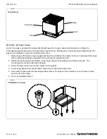
2.  Lift the flue riser off the front of the skid (see Figure 3) and set it aside for installation later in this procedure. 
3.  Pull the shelf assembly out from under the base and set it aside for installation later in this procedure. 
4.  Unbolt the shipping hold-down brackets from the skid, then remove the brackets from the range. 
5.  If the range is to be installed on legs, go to Step 2a. 

If the range is to be installed on casters, go to Step 2b. 

O

WNER

M

ANUAL 

1182499 P

AGE 

13

 OF 

40 

Summary of Contents for Southbend 436A-CE

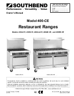
Page 1: ...t Oven Ranges 436A CE 436D CE 460AA CE 460AD CE and 460DD CE First Choice Group Blakeney Way Kingswood Lakeside Cannock Staffs WS11 8LD TEL 01543 577778 FAX 01543504141 Email enquires firstchoice cs c...

Page 2: ...is appliance shall be installed in conformity with the current regulations and used only in a well ventilated location Consult the instructions before installing and using the appliance Improper insta...

Page 3: ...n a prominent location detailed instructions to be followed in the event the operator smells gas Obtain the instructions from the local gas supplier WARNING BURN HAZARD Contact with hot surfaces will...

Page 4: ...is divided into six sections Introduction 3 Specifications 4 Operation 8 Cleaning Maintenance 11 Installation 13 Service 19 The serial plate is located on the right side of the range see Figure 1 belo...

Page 5: ...or commercial use and is only for professional use It shall be used by trained qualified people CLEARANCES WARNING MINIMUM CLEARANCES FROM COMBUSTIBLE CONSTRUCTION There must be adequate clearance bet...

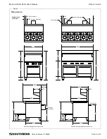
Page 6: ...2 572 787 787 152 152 940 940 394 394 318 318 768 64 152 64 152 152 610 Electrical Connections Electrical Connection Gas Connection Gas Connection Side View of Ranges with Convection Oven Side View of...

Page 7: ...flue outlet of the oven and connected to the flue In case of unsatisfactory performance on any appliance check the appliance with the exhaust fan in the OFF position Do this only long enough to check...

Page 8: ...aks All connections must be checked for leaks after the range has been put into operation Test pressure should not exceed 3 47 kPa 14 W C ELECTRICAL REQUIREMENTS Ranges with a convection oven require...

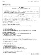
Page 9: ...g 1 Make sure all of the control valves are in the OFF position 2 Turn on the gas supply 3 Light the pilots as described below 4 Light the oven first and then wait six minutes before lighting top burn...

Page 10: ...problem only occurs for the range and if the above solutions to do not solve the problem call for repair service TROUBLESHOOTING CONVECTION OVEN COOKING PROBLEMS If then Cakes are dark on the sides an...

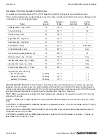
Page 11: ...rare 60 C internal 31 min kg 120 C 1 1 2 medium 65 C internal 35 min kg 120 C 1 1 2 well done 70 C internal 39 min kg 120 C 1 1 2 FROZEN ENTREE PRODUCTS Punch holes in lid before heating Tent lid if p...

Page 12: ...m Clean by rubbing with strong detergent and Brillo pad or similar scrubber Spill overs should be cleaned from the bottom as soon as possible to prevent carbonizing and a burnt on condition For stubbo...

Page 13: ...DO NOT USE ORDINARY STEEL WOOL as any particles left on the surface will rust and further spoil the appearance of the finish NEVER USE A WIRE BRUSH STEEL SCOURING PADS EXCEPT STAINLESS SCRAPER FILE O...

Page 14: ...sponsibility Any problem due to improper ventilation will not be covered by warranty STEP 1 UNPACKING IMMEDIATELY INSPECT FOR SHIPPING DAMAGE All containers should be examined for damage before and du...

Page 15: ...attached For safety shore up and support the range with an adequate blocking arrangement strong enough to support the load 2 Attach the four leg pads to the bottom of the range using the lock washers...

Page 16: ...bottom of the range using the lock washers and machine screws The mounting holes are pre drilled and threaded 3 Screw the casters into the holes in the centers of the leg pads Install the casters that...

Page 17: ...are turned off prior to disconnecting After reconnecting be sure all controls are turned off and all pilots are lit NOTICE Adequate means must be provided to limit the movement of the appliance witho...

Page 18: ...re through the strain relief fitting to the terminal block Insert the supply wires one each into the two poles of the terminal block and tighten the screws Insert the ground wire into the grounding lu...

Page 19: ...that all screws and bolts are tightened 2 Check that the electrical and gas connections have been made correctly 3 With the range in the position that it will be operated check that the range is leve...

Page 20: ...s in operation at initial installation check type of gas and manifold pressure and compare with information listed on the serial plate This section contains troubleshooting flowcharts procedures and e...

Page 21: ...ilot gas not adjusted properly Clogged orifice Draft condition Improper ventilation system Air in gas line Thermocouple bad Figure 8 Troubleshooting Open Top Burners Open top burners are not working c...

Page 22: ...fety valve and put a flame to the pilot Does the pilot light No Yes Check that the oven pilot adjustment on the manifold is open Continue to hold the red button for 30 seconds The pilot should remain...

Page 23: ...n is hot No Yes DISCONNECT POWER AT CIRCUIT BREAKER Check that there are no air flow obstructions around the range Check all wiring for loose connections or breaks Check that the blower motor is not p...

Page 24: ...Does the measured voltage match the rated voltage of the range Yes No Check power supply to range Re assemble the switch cover and valve panel Turn on the blower control switch and open the oven door...

Page 25: ...the white and red wires is also approximately 1 9 ohms If either resistance is incorrect replace the blower motor ADJUSTMENT OF GAS PRESSURE REGULATOR The pressure regulator is factory set at 0 99 kP...

Page 26: ...e sized for the specified gas supply The burner flame characteristics are controlled by varying the primary air mixer cap There should be a clear blue flame with a distinct inner cone at each port Exc...

Page 27: ...ange the thermostat calibration If it is outside of the temperature range continue with this procedure 7 Look into the thermostat knob to see the calibration screw in the stem see illustration on page...

Page 28: ...L 400 CE RESTAURANT RANGES SERVICE Figure 13 Figure 13 Oven Thermostat Calibration and Bypass Flame Adjustment Bypass Adjustor Calibration Stem Bezel Knob Insert Knob OWNER S MANUAL 1182499 PAGE 27 OF...

Page 29: ...SERVICE MODEL 400 CE RESTAURANT RANGES Figure 14 Wiring Diagram for 208 230 Volt Models PAGE 28 OF 40 OWNER S MANUAL 1182499...

Page 30: ...ternal Parts 30 Open Top Burner Parts 31 Convection Oven Parts 32 Standard Oven Parts 34 Figure 15 Leg and Caster Parts 5 4 1 2 3 Key Part Number Qty Description 1 1146201 16 1 4 X 20 X 3 4 HEX HEAD 2...

Page 31: ...0766 1 FLUE RISER ASSEMBLY 22 5 X 36 1181150 1 FLUE RISER ASSEMBLY 10 X 36 1180768 1 FLUE RISER ASSEMBLY 22 5 X 60 1181152 1 FLUE RISER ASSEMBLY 10 X 60 3 1180783 1 2 KICK PANEL 4 1172716 1 2 LOGO PLA...

Page 32: ...BODY 6 1182287 3 5 BRACKET REAR TUBE SUPPORT 7 1148301 3 5 NUT BRASS JAM 8 1008737 6 10 HOOD ORIFICE 37 NATURAL GAS 1008754 6 10 HOOD ORIFICE 54 LP GAS 9 1177111 6 10 BURNER ASSEMBLY 10 1182489 3 5 T...

Page 33: ...08 240 VOLT 1177452 1 MOTOR 1 3 HP 115VOLT 12 1181117 1 BRACKET DOOR SWITCH 13 1177567 1 SWITCH DOOR 14 1180859 1 QUADRANT ASSEMBLY 15 1180834 1 OVEN BAFFLE CO 16 1180841 2 BRACKET OVEN BAFFLE 17 1180...

Page 34: ...L 400 CE RESTAURANT RANGES SERVICE Figure 18 3 4 1 2 5 6 7 8 9 10 13 14 11 12 15 16 17 18 19 20 23 24 21 22 25 26 Convection Oven Parts See parts list on previous page OWNER S MANUAL 1182499 PAGE 33 O...

Page 35: ...80859 1 QUADRANT ASSEMBLY 6 1164278 1 SA BURNER NATURAL GAS 1164279 1 SA BURNER LP GAS 7 1186683 1 KNOB CE OVEN THERMOSTAT DIAL 8 1182497 1 BEZEL CE OVEN THERMOSTAT KNOB 9 1186680 1 THERMOSTAT 1182493...

Page 36: ...MODEL 400 CE RESTAURANT RANGES SERVICE Figure 19 3 4 1 2 5 6 7 8 9 10 13 14 11 12 Standard Oven Parts See parts list on previous page OWNER S MANUAL 1182499 PAGE 35 OF 40...

Page 37: ...MODEL 400 CE RESTAURANT RANGES Notes PAGE 36 OF 40 OWNER S MANUAL 1182499...

Page 38: ...MODEL 400 CE RESTAURANT RANGES Notes OWNER S MANUAL 1182499 PAGE 37 OF 40...

Page 39: ...MODEL 400 CE RESTAURANT RANGES Notes PAGE 38 OF 40 OWNER S MANUAL 1182499...

Page 40: ...MODEL 400 CE RESTAURANT RANGES Notes OWNER S MANUAL 1182499 PAGE 39 OF 40...

Page 41: ...l recognize however that replacement parts and occasional professional service may be necessary to extend the useful life of this appliance When service is needed contact a Southbend Authorized Servic...

Reviews: