S
ERVICE
M
ODEL
400-CE R
ESTAURANT
R
ANGES
Figure 12
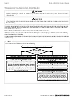
Convection-Oven Blower Does Not Run, Continued
(Continuing from previous page.)
DISCONNECT POWER AT CIRCUIT BREAKER.
Is there voltage?
No
Yes
Remove the wire terminal cover from the blower motor.
Check that the common wire is connected to the motor black wire.
Reconnect the power supply and turn on blower-control switch.
Use a voltmeter to measure the voltage between the black wire and
the white wire.
DISCONNECT POWER AT CIRCUIT BREAKER.
Check that the red wire is capped off.
Remove the wire nuts from the black and the white wires. Check
that in each case the wires are twisted together securely.
Check that the neutral wire is connected to the white wire.
CHECK THAT POWER IS DISCONNECTED
AT CIRCUIT BREAKER.
Check all wiring for loose terminals or breaks.
Remove the wire nuts from the red, white, and black wires.
Check that the resistance across the white and black wires is
approximately 1.9 ohms. Check that the resistance across the
white and red wires is also approximately 1.9 ohms. If either
resistance is incorrect, replace the blower motor.
A
DJUSTMENT OF
G
AS
P
RESSURE
R
EGULATOR
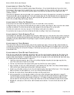
The pressure regulator is factory set at 0.99 kPa (4" W.C.) for natural gas and 2.48 kPa (10" W.C.) for propane gas.
To check the manifold pressure:
1. Turn all thermostats and burner valves to OFF position.
2. Turn main gas valve to entire range off.
3. Remove valve panels and locate the small plug in the manifold.
4. Remove plug and install a fitting appropriate to connect a manometer.
5. Turn on main gas to range and light pilots.
6. Turn all burners and ovens to full ON position and read manometer.
7. If manometer does not read 0.99 kPa (4" W.C.) for natural gas, or 2.48 kPa (10" W.C.) for propane gas, adjust
regulator (if gas pressure is correct go to Step 10).
8. Remove cap from top of regulator.
9. With a screwdriver rotate regulator adjustment screw clockwise to increase, or counterclockwise to decrease,
pressure until manometer shows correct reading.
10. Repeat steps 1 and 2.
11. Remove manometer fitting and replace plug in manifold.
12. Turn on main gas to range and light pilots.
13. Replace valve panels.
P
AGE
24
OF
40
O
WNER
’
S
M
ANUAL
1182499
Summary of Contents for Southbend 436A-CE
Page 37: ...MODEL 400 CE RESTAURANT RANGES Notes PAGE 36 OF 40 OWNER S MANUAL 1182499...
Page 38: ...MODEL 400 CE RESTAURANT RANGES Notes OWNER S MANUAL 1182499 PAGE 37 OF 40...
Page 39: ...MODEL 400 CE RESTAURANT RANGES Notes PAGE 38 OF 40 OWNER S MANUAL 1182499...
Page 40: ...MODEL 400 CE RESTAURANT RANGES Notes OWNER S MANUAL 1182499 PAGE 39 OF 40...

