background image


The following regeneration cycles are listed in the factory programmed sequence.  Each cycle in the 
regeneration process may be advanced without waiting for the programmed cycle duration, for installation, 
troubleshooting, or maintenance purposes. 

Cycle:  

BRINE FILL


Cycle:  

SERVICE 


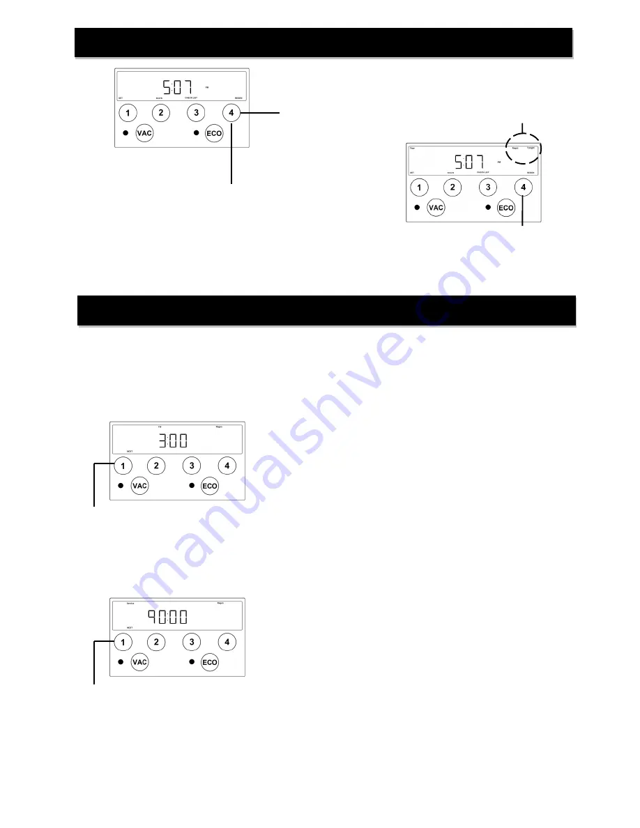
Initiating Regeneration 

Momentarily pressing and releasing the ‘REGEN’ button will 
cause the Regen Tonight indicator to illuminate on the top left 
side of the display.  The regeneration process will begin at the 
next programmed time-of-regeneration (factory preset for 2:00 
AM) 


Press ‘NEXT’ button to advance to 
Backwash Cycle. 

Pressing and HOLDING the ‘REGEN’ button for approximately 
3 seconds will initiate an immediate regeneration.  
 

NOTE:  The regeneration cycle will disable the ‘Regen 

Tonight’ indicator (if illuminated).  The regeneration cycle will 
also reset the gallons remaining until next regeneration and the 
days override interval. 

Regeneration Process 

Momentarily pressing and releasing 
the ‘REGEN’ button again will cancel 
the delayed regeneration cycle. 


1. The Fill and Regen indicators will be illuminated on the display. 
2. The control valve will advance to the brine fill position and start adding 
 

water to the brine tank.   

3. The cycle duration will begin to count down on the display once the 
 

control valve is in the proper position.  The cycle duration is 


dictated by either the programmed salt dosage setting or the 


ECO calculated salt dosage (if activated). 

4. This cycle occurs 90 minutes prior to the scheduled regeneration 
 

time.   (Regeneration is factory preset at 2:00 AM, so Brine Fill 


cycle would occur at 12:30 AM)  

5. Treated (soft) water is still available during this cycle. 

1. The Service and Regen indicators will be illuminated on the display. 
2. The control valve will advance to the Service (Home) position.   
3. The cycle duration will begin to count down on the display once the 
 

control valve is in the proper position.   

4. This cycle allows the fresh water that has been added to the brine 
 

tank sufficient time to dissolve the salt to make saturated brine. 

5. Treated (soft) water is still available during this cycle. 

Press ‘NEXT’ button to advance to 
Service Cycle. 

Summary of Contents for XTS30

Page 1: ...Sales LLC 12630 US Highway 33 N Churubusco IN 46723 Phone 260 693 1972 Fax 260 693 0602 XTS Series Instruction Manual 180122 docx XTS Series Water Softening System Installation Instructions and Owner s Manual ...

Page 2: ...splay and Operation Page 8 Regeneration Page 9 Statistics Page 11 Installer Settings Page 11 Vacation Mode Page 14 Eco Mode Page 14 Component Parts Breakdown List Page 15 Control Valve Parts Breakdown List Page 16 Installation Fitting Assemblies Page 17 Troubleshooting Page 19 Ten Year Limited Warranty Page 21 Table of Contents ...

Page 3: ...14 Neutral water has a pH of 7 0 lower values indicate acidic water If your pH is below 6 8 you may consider installing an acid neutralizer before the water softener to elevate the pH Iron A naturally occurring metallic element Iron levels in excess of 0 3 milligrams liter mg l combine with oxygen causing orange or red rust stains on plumbing fixtures Iron exists in some water sources in clear wat...

Page 4: ...nd filter tank Install with at least 10 of pipe before the water heater to prevent thermal damage to the equipment An expansion tank may need to be installed in the line to the water heater in order to allow for thermal expansion and comply with local plumbing codes 4 The water softener should not be subject to freezing temperatures 5 Ensure that any cartridge or in line type filter installed prio...

Page 5: ...pressing the SET button Home screen displays current time of day Prerecorded Basic Installation Press SET button to set incoming iron concentration Ensure the Iron indicator is illuminated on the left side of the display and using the and buttons set the incoming iron concentration NOTE While a water softener can be reasonably expected to remove small amounts of clear water iron for best performan...

Page 6: ... Step 7 Connect 3 8 tubing between control valve and salt tank Step 8 Add 3 gallons of water to brine tank Step 9 Add at least 40 pounds of water softener salt to brine tank Step 10 DO NOT TAKE ANY ACTION UNTIL YOU HAVE LISTENED TO THE REMAINING INSTRUCTIONS A Advance control to BACKWASH B Crack open the inlet side of the bypass valve C Allow unit to slowly fill pushing air out drain line D When a...

Page 7: ...he backwash rate of the softener refer to specifications and flow rate DISCHARGE END OF THE DRAIN LINE MUST BE FIRMLY SECURED There must be an air gap at the end of the drain line to prevent siphoning of waste water and meet plumbing code Total length of drain line should be 15 or less AVOID OVERHEAD DRAINS STEP 7 Connect one end of the 3 8 brine line to the control valve quick connect fitting Ins...

Page 8: ... Filling the mineral tank with the control valve in the backwash position will force any trapped air to the drain When all air has been purged from the system and only water is running to the drain advance the control valve to the BRINE DRAW cycle Fully rotate both the inlet and outlet knobs of the bypass valve to the Service position STEP 13 Verify that the water level in the brine tank is droppi...

Page 9: ... Active prompts for user input buttons 4 User Input buttons Vacation Mode button and indicator light Eco Mode button and indicator light Display and Operation Setting Time Home screen displays current time of day Press SET button to access time set screen Using and set the current time of day hours Note the AM and PM indicator and set the time accordingly Press NEXT button to set current minutes U...

Page 10: ... REGEN button again will cancel the delayed regeneration cycle 1 The Fill and Regen indicators will be illuminated on the display 2 The control valve will advance to the brine fill position and start adding water to the brine tank 3 The cycle duration will begin to count down on the display once the control valve is in the proper position The cycle duration is dictated by either the programmed sal...

Page 11: ...e Brine Draw position 3 The cycle duration will begin to count down on the display once the control valve is in the proper position 4 Water will flow through the injector causing suction to draw the brine solution out of the salt tank The brine solution will flow down through the resin and out the drain 5 Softening systems with a single mineral tank will have an internal bypass to allow untreated ...

Page 12: ...isplayed on top left corner of screen whether water is being used or not Display registers flow rate in gallons per minute Pressing NEXT button advances screen to volume remaining Volume remaining screen displays the number of gallons that can be treated before the scheduled regeneration cycle NOTE Due to the reserve capacity the softener may still provide softened water even with zero gallons dis...

Page 13: ... designated period of no regeneration cycles The override interval will reset after every regeneration cycle whether initiated manually or by volume The day override function will be disabled if the VACATION mode is active Press NEXT button to set REGENERATION TIME hours Ensure the Regen Time indicator is illuminated Using and set the desired time of regeneration hours Note the AM and PM indicator...

Page 14: ...ine NOTE Minimum recommended time is 90 minutes Press NEXT button to set cycle 3 duration Ensure the Backwash and Minutes indicators are illuminated Using and set the desired length of time for BACKWASH cycle Press NEXT button to set cycle 4 duration Ensure the Draw and Minutes indicators are illuminated Using and set the desired length of time for BRINE DRAW cycle Press NEXT button to set cycle 5...

Page 15: ...ated water use The water softener stores historical daily water use data If the next day s anticipated water use requires more softening capacity than is currently available the softener will initiate a regeneration process using a fractional portion of the programmed salt setting This partial salt regeneration recovers only the depleted portion of the softening capacity This proportional regenera...

Page 16: ...tributor D100S 48 D100S 54 D100S 48 D Resin Qty 2 H05P Qty 3 H05P Qty 4 H05P E 1 4 X 1 8 Gravel Qty 1 QC20 Qty 1 QC20 Qty 1 QC20 F Brine Tank Assy BTSQ1833ASSY BTSQ1833ASSY BTSQ1833ASSY G Overflow Fitting BT OVERFLO BT OVERFLO BT OVERFLO H Safety Brine Valve SBV14ASSY SBV14ASSY SBV14ASSY I Salt Platform BTSG18SQ BTSG18SQ BTSG18SQ J Bypass BP 213 BP 213 BP 213 Component Parts Breakdown ...

Page 17: ...y 15 7779K420 MICRO Micro Switch 2 required 5 CAB945 Piston and Rod Assembly 16 EBA910 90 Bypass Elbow 6 TSS900 Seal Cartridge Assembly 17 BP 213 Bypass Valve 7 RVS932 Injector Assembly w o rings 18 EBA975 NPT Elbow includes nut and o ring 8 FS165 Injector Filter Screen EBA900 1 NPT Elbow includes nut and o ring 9 OR344 Valve to Tank Adaptor O Ring EBA915 1 NPT Elbow includes nut and o ring 10 OR3...

Page 18: ...1 4 C 102 Connector Nut 1 4 C 102 Connector Nut 1 1 1 2 PVC MALE NPT ELBOW PVC MALE NPT ELBOW Ref Part Description Qty Ref Part Description Qty EBA915 1 1 2 Elbow Assembly 1 EBA975 3 4 Elbow Assembly 1 1 EB150 1 5 Elbow 1 1 EB750 3 4 Elbow 1 2 OR324 O ring 324 1 2 OR324 O ring 324 1 3 C 101 Split Ring Retainer 1 3 C 101 Split Ring Retainer 1 4 C 102 Connector Nut 1 4 C 102 Connector Nut 1 2 requir...

Page 19: ...ng Assembly 1 1 TC101 1 1 Straight 1 2 OR324 O ring 324 not shown 1 3 C 101 Split Ring Retainer not shown 1 4 C 102 Connector Nut 1 3 4 QUICK CONNECT Ref Part Description Qty QFNCR4 3 4 Quick Connect Assembly 1 Installation Fitting Assemblies cont 1 4 2 required 2 required ...

Page 20: ...ter pressure A Softener too small for application A Check application requirements and resize water softener as required B Foreign material buildup in plumbing system or water softener B Clean or replace plumbing as necessary additional treatment equipment may be required 5 Loss of resin through drain line A Air in water system A1 Check for low water table conditions in well A2 Check for positive ...

Page 21: ...then rinse cycle 9 Water leaks to drain continuously A Foreign material in control valve A Remove and inspect piston and seal kit Replace as necessary B Drive motor stopped during regeneration cycle B Check for obstruction in piston and seals Replace drive motor Inspect condition of power head gears C Control valve continuously cycling C See Problem 10 D Internal valve seal leak D Replace seals an...

Page 22: ...ld a defect or malfunction occur contact the dealer that you purchased the product from If you are unable to contact the dealer contact First Sales LLC 260 693 1972 We will require a full description of the problem model number date of purchase and selling dealer s business name and address We assume no warranty liability in connection with this water conditioner other than specified herein This w...

Reviews: