Alarm and Starter System
www.firstechdata.com
CM900 Master Guide
Copyright 2018 Fi rst ech ,
LLC.
Page 16
Pin 7 Green - Ignition 12V positive (+)
output and input. This wire must be connected to
the vehicle’s
ignition for remote start and valet / remote programming. The proper wire will test 0V with the key in
the off position, 12 V (+) while the key is in the on position and 12V (+) during crank.
Pin 8 Black - Ground negative (-) input. This wire must be connected to
the vehicle’s chassis ground. Make sure
no paint or rust is on the mounting surface. We recommend connecting this wire first.
IF you’re having
trouble locating a good ground source you can use PIN # 4 at the Standard OBD II connection
Connector 2 (CN2), Black 20-Pin: Blade Connector
This connector is used only if you are installing a Blade-AL or Blade-TB. The wiring harness for this
connector only comes with the Blade cartridge. Please refer to the Blade install guide for wire description
http://compustar.idatalink.com.
Connector 3 (CN3) CM900AS, Grey 18-Pin: Input/Output harness (I/O harness)
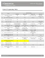
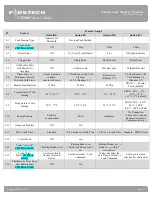
IMPORTANT: Pins 1-7 are programmable for up to 19 different output types. Refer to Special Option
Group 2 for complete details. Note: These inputs/outputs are subject to change, for the latest software
update and feature table please visit compustar.idatalink.com or www.firstechdata.com
Pin 1 Green/White - (fixed output) Parking light 250mA negative (-) output. This will provide output whenever
the parking lights are activated for lock, unlock, remote start, diagnostics, and programming the proper
wire in the vehicle will test (-) when the parking light switch is in the on position.
Note: There are 18 additional POC setting options for this POC.
Pin 2 Blue/Lt. Green - [POC 2] Lock 250mA, 800mS (-) negative output: This is an optional output that
will provide only negative (-) output pulse for locking doors. System will lock doors and arm alarm.
IMPORTANT: You must reverse polarity for (+) trigger door lock systems using the FT-DM700, FT- DM600
or relays. For additional lock settings review Option Group 1.
Note: There are 18 additional POC setting options for this POC
Pin 3 Blue - [POC 3] Unlock 250mA, 800mS (-) negative output: This is an optional output that will provide only a
negative (-) output pulse for unlocking doors. System will unlock doors and disarm alarm. IMPORTANT:
You must reverse polarity for (+) trigger door lock systems using the FT-DM700, FT- DM600 or relays. For
additional lock settings review Option Group 1.
Note: There are 18 additional POC setting options for this POC
Pin 4 Black - [POC 4] Status/Ground while running (GWR) 250mA latched negative (-) output: This is an optional
output that will provide a latched negative (-) output 250mS before the ignition turns on, stays on throughout
the remote start duration and will be the last to shut off. This wire is most commonly used to trigger bypass /
transponder modules. Note: There are 18 additional POC setting options for this POC
Pin 5 Orange - [POC 5] Factory Alarm Arm (FAA) 250mA, 800mS negative (-) output: This is an optional output
that will provide a (-) pulse during lock, after crank and again after the remote start shuts down. The FAA
output timing can be configured using feature 1-05.
Note: There are 18 additional POC setting options for this POC

