Alarm and Starter System
www.firstechdata.com
CM900 Master Guide
Copyright 2018 Fi rst ech ,
LLC.
Page 19
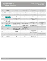
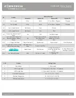
Pin 6 Orange/White - [POC 6] Factory Alarm Disarm (FAD) 250mA, 800mS negative (-) output: This
output will provide a (-) pulse during unlock and every time prior to the GWR (ground when running:
aka. Status output) turning on during the remote start sequence. It is typically used to disarm factory
security systems. Note: There are 18 additional POC setting options for this POC
Pin 7 White - [POC 7] Horn:250mA negative (-) output. This is an optional output that will provide a fixed
30mS negative output when triggered by the remote(s). The output control is based on feature 3-08
option setting. Note: There are 18 additional POC setting options for this POC
Pin 8 Gray/Black - Hood Pin negative (-) (default setting) input: This input is a safety shut down and alarm trigger.
It prevents the vehicle from remote starting while the hood is open and triggers the alarm if the hood is opened
while the alarm is armed. You can connect this wire to the hood pin supplied with this
kit, or to a wire in the vehicle that shows (-) only while the hood is open.
Pin 9 Light Blue/White - Brake 12V positive (+) input: This wire must be connected as it provides a
shut down for the remote start. It is also required to enter and exit Valet Mode. The proper wire will test
(+) 12V while the foot brake is pressed.
Pin 10 RED/White - Trigger start (-) input: This wire can be used to activate/deactivate the remote start sequence
when it receives a ground pulse based on feature 2-04 option setting 1, 2, or 3 pulses.
Pin 11 RED - Positive (+) input: Trigger start which will activate/deactivate the remote start sequence when it
receives a positive or B+ pulse based on feature 2-04 option setting 1, 2, or 3 pulses is the default setting.
This can be done with a door lock motor output being operated by a factory keyless entry or another
external source. There are additional options for this Input please check feature 4-10
Pin 12 Yellow/Black - Engine sensing input (A/C): This wire is connected
to the vehicle’s Tach or Alternator wire
and is required when using the tach and alternator sense setting. (You can also connect this wire to the battery
(+) post when using voltage sense to make it more accurate) IMPORTANT: To change engine-sensing
modes, you must change Option 2-10. Tach programming procedure can be found on page 13.
Connector 4 (CN4), 6-Pin Note: This harness is not included with CM7 wire harness kits. The Lock (POC
2), Unlock (POC 3), Trunk release outputs have been moved to CN3 I/O harness and are
programmable outputs. This connector will still be available for any Firstech lock harness. (FT-DM600
or FT-DM700)
Pin 1 None - 12v B+ constant output: available when using a Firstech door lock Module DM600, DM700
Pin 2 Violet/White - Trunk release 250mA, 800mS negative (-) output: This is an optional output that will
release the trunk. Use CN1, Pin 2 if the vehicle is equipped with a (+) trunk release. System will unlock
doors and disarm alarm prior to trunk release.
Pin 3 Orange/Black - 2nd Unlock 250mA, 800mS negative (-) output: This is an optional output that will
provide a (-
) pulse for driver’s priority door lock. IMPORTANT: You must isolate the driver’s door and
set feature 1-03 to option 2 (on).


