- 10 -
GOES ANTENNA
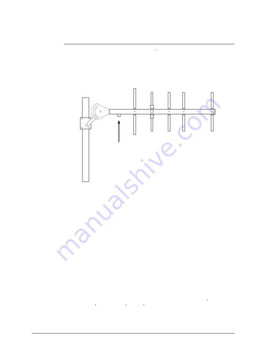
The GOES antenna is used by the HDL1-G5 s internal transmitter to transmit to the
signal to the GOES satellite. The GOES antenna is a 50 ohm, Yagi antenna with
right hand circular polarization, 11dBic gain and a nominal VSWR of 1.5.
The following procedure details the mounting procedure for the GOES Antenna.
#1
#2
#3
#4
#5
Connector should always
face down when antenna
is mounted.
#1 - D3
#2 - D2
#3 - D1
#4 - DE
#5 - R
Figure 4.
The GOES Antenna
1. Install the two U-bolts in the mounting bracket, using four split lock washers and
four 5/16 hex nuts.
2. Attach the antenna to the mounting bracket using two 3/8 x 2" bolts, four external
tooth lock washers, and two 3/8 nuts.
3. Conductive grease that is compatible with aluminum is applied to the antenna
element threads. Attach the elements finger-tight to the antenna boom. There is
a number stamped on the end of each element. Beginning at the end and
working toward the mount, install elements 1, 2, 3, 4 and 5 in order.
4. Mount the antenna assembly on a vertical pipe to allow for accurate angle
adjustment. The antenna must be free to rotate around the pipe so it can be
aimed at the satellite once the GPS receiver has synchronized with the GPS
satellites.
5. Inclination and bearing required to properly align the antenna with the satellite
can be found using the front panel of the HDL1-G5. Start by pressing the red
MAIN MENU button on the HDL1-G5 front panel. Then select E: Telemetry
Information followed by Antenna . The bearing information shown on the
HDL1-G5 display (see Figure 5) is for true north and will need to be adjusted for
magnetic north based on the installation area.
Summary of Contents for HDL1
Page 1: ...HDL1 HDL1 G5 Data Logger Operating Manual...
Page 2: ......
Page 8: ...iv THIS PAGE INTENTIONALLY LEFT BLANK...
Page 12: ...4 THIS PAGE INTENTIONALLY LEFT BLANK...
Page 20: ...12 THIS PAGE INTENTIONALLY LEFT BLANK...


