MANUAL for the Stages Control Panel | CCE2.0
22
6. Connections
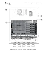
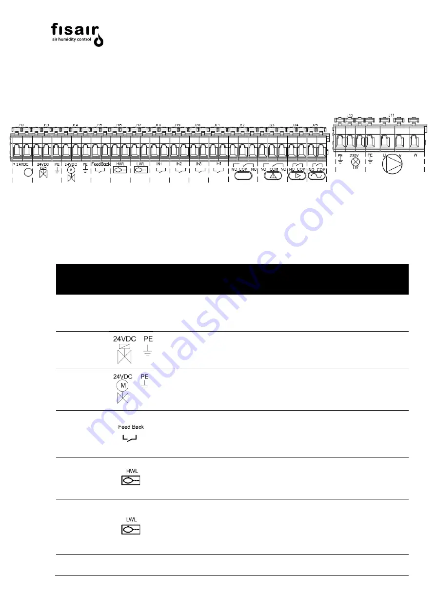
1) Connect the standard accessories to the SEF-028.1 card according to
Figure
4.1.
Figure 4.1: SEF-028.1 card
Type of
connection
Symbol
Connection
Description
Max. Power
Max. Voltage
Optional.
+24VDC
J12*
Water drain/emptying motor-valve
supply
5W
24Vdc
Mandatory
J13
Water supply solenoid valve
50W
24Vdc
Mandatory
J14*
Water drain/emptying motor valve
40W
24Vdc
Mandatory
J15*
Emptying motor valve feedback
position (limit switch opened)
Not powered
Mandatory
J16
Maximum water level sensor (NC
contact)
Not powered
Mandatory
J17
Minimum water level sensor (NO
contact)
Not powered
*See next page
Summary of Contents for CCE2.0
Page 2: ...MANUAL for the Stages Control Panel CCE2 0 2 ...
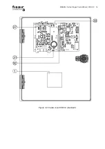
Page 14: ...MANUAL for the Stages Control Panel CCE2 0 14 Figure 3 4 Inside cover CCE2 0 standard ...
Page 53: ...MANUAL for the Stages Control Panel CCE2 0 53 13 Declaration of conformity 13 1 D C Machine ...
Page 54: ...MANUAL for the Stages Control Panel CCE2 0 54 13 2 D C Partly completed machinery ...
Page 55: ...MANUAL for the Stages Control Panel CCE2 0 55 14 Warranty ...
Page 56: ...MANUAL for the Stages Control Panel CCE2 0 56 ...
Page 57: ...IÓN F ...
Page 58: ...IÓN ...
Page 59: ...IÓN MAN P Ev1 Mv1 P P ...
Page 60: ...F IÓN ...
Page 61: ...IÓN ...
Page 62: ...IÓN MAN P Ev1 Mv1 P P ...

