MANUAL for the Stages Control Panel | CCE2.0
24
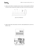
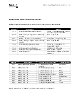
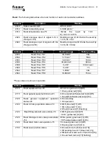
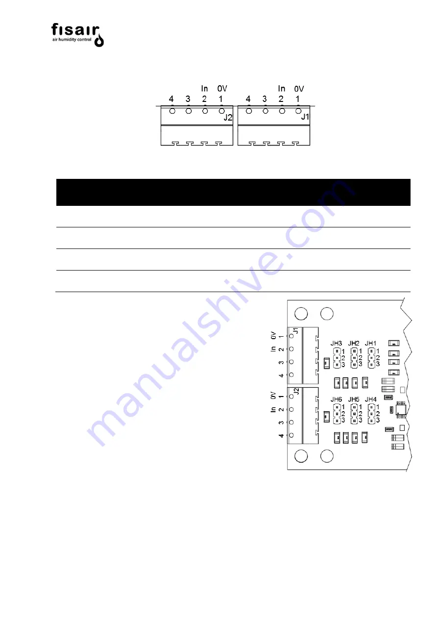
2) Connect (*) the regulated analog external signal to the MPCB-IN01 card according to figure 4.2.
Figure 4.2:
MPCB-IN01
Card (Analog signal connection)
Type of
connection
Symbol
Connection
Description
Max. Power
Max. Voltage
Mandatory
0V
1
J1.1
Reference signal (0V)
-
Mandatory
IN
2
J1.2
Analog signal (0-10V)
-
Mandatory
0V
1
J2.1
Reference signal 0V
-
Mandatory
IN
2
J2.2
Analog signal 4-20 mA
-
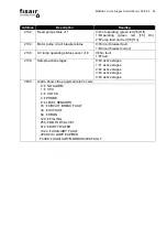
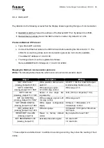
A.
Regulated analog signal of stage control 0..10 V
DC
.
Connect this signal to Jumper 1 (J1)
Connect Jumper JH1, JH2 and JH3 in position 1-2
B.
Regulated analog signal of stage control 4..20 mA .
Connect this signal to Jumper 2 (J2)
Connect jumper JH4 in position 1-2 and Jumper JH5
and JH6 in position 2-3
* When the data bus communication options are available, the analogue signal regulation card
MPCB-IN01 must not be connected, as communication will be via the data bus. If you do not want
to regulate by data bus, the card must be connected. In these cases, the card is delivered
disconnected.
Figure 4.3: MPCB-IN01 card
(Jumpers detail)
Summary of Contents for CCE2.0
Page 2: ...MANUAL for the Stages Control Panel CCE2 0 2 ...
Page 14: ...MANUAL for the Stages Control Panel CCE2 0 14 Figure 3 4 Inside cover CCE2 0 standard ...
Page 53: ...MANUAL for the Stages Control Panel CCE2 0 53 13 Declaration of conformity 13 1 D C Machine ...
Page 54: ...MANUAL for the Stages Control Panel CCE2 0 54 13 2 D C Partly completed machinery ...
Page 55: ...MANUAL for the Stages Control Panel CCE2 0 55 14 Warranty ...
Page 56: ...MANUAL for the Stages Control Panel CCE2 0 56 ...
Page 57: ...IÓN F ...
Page 58: ...IÓN ...
Page 59: ...IÓN MAN P Ev1 Mv1 P P ...
Page 60: ...F IÓN ...
Page 61: ...IÓN ...
Page 62: ...IÓN MAN P Ev1 Mv1 P P ...

