background image

MANUAL for the Stages Control Panel | CCE2.0 


1.  Safety instructions  


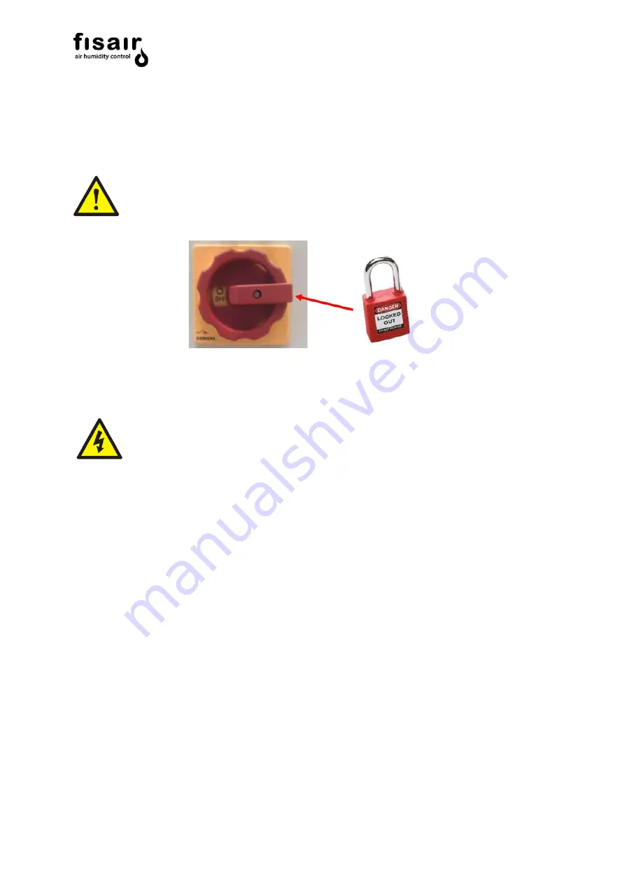
Need to consign the control panel for maintenance and revision 


The machine controlled by CCE2.0 panel must not be manipulated when it is in operation. 
Facing any problem that is detected in the machine during its operation

, disconnect it 

and set the main switch of the CCE2.0 panel using a padlock.


Installation of a residual current device in the power supply line. 


The installer has to install a specific residual current device in the machine's electrical 
power circuit. 


FISAIR  disclaims  any  liability  if  not  all  the  installation  and  operating  instructions  it  has 
provided are complied with; if the products have been modified or altered without the written 
consent  of  FISAIR;  or  if  the  products  have  been  subjected  to  improper  use,  mishandling, 
alteration,  improper  maintenance  or  show  signs  of  negligent  use  or  being  involved  in  an 
accident. These situations could include an incorrect power connection, impacts with other 
objects, removal or disarming of security fittings/measures, etc. 


Summary of Contents for CCE2.0

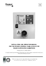
Page 1: ... fisair com fisair com INSTALLATION AND OPERATION MANUAL FOR THE STAGES CONTROL PANEL CCE2 0 FOR FISAIR EVAPORATIVE HUMIDIFIERS Software version 2 1 MCCE2 0 EN 21 1 In compliance with the Rules and Standards of the European Union on Machine Safety it is essential to read this protocol carefully before installing any equipment ...

Page 2: ...MANUAL for the Stages Control Panel CCE2 0 2 ...

Page 3: ...g never 31 8 2 Configuration Prior to Start Up Pre Start up 32 8 3 Stages configuration 33 8 4 Conf 0 10V or 4 20 mA 34 8 5 UV lamp configuration 34 8 6 Bus configuration 35 8 6 1 MODBUS TCP IP y RTU 35 8 6 2 BACnet IP 39 8 7 Language 43 8 8 Date 43 9 Settings 44 9 1 SET POINT µS cm if applicable 44 9 2 TIMER T01 ex SW1 AB 44 9 3 TIMER T02 ex SW1 CD 45 9 4 TIMER T03 ex SW2 AB 45 9 5 TIMER T04 ex S...

Page 4: ...or the Stages Control Panel CCE2 0 4 13 Declaration of conformity 53 13 1 D C Machine 53 13 2 D C Partly completed machinery 54 14 Warranty 55 ANEX E09489 C WIRING DIAGRAM 230VAC E09490 C WIRING DIAGRAM 400VAC ...

Page 5: ...ly line The installer has to install a specific residual current device in the machine s electrical power circuit FISAIR disclaims any liability if not all the installation and operating instructions it has provided are complied with if the products have been modified or altered without the written consent of FISAIR or if the products have been subjected to improper use mishandling alteration impr...

Page 6: ...ges all the field components of FISAIR Evaporative Humidifiers Water recirculation pump Detector of the minimum and maximum basin water level Basin water supply solenoid valve Emptying draining motor valve in the basin Solenoid valves for different Stages UV lamp water treatment system optional Water conductivity control optional Modbus TCP IP optional Modbus RTU optional BACnet IP optional For th...

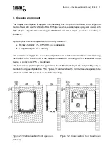
Page 7: ... humidity 5 95 HR no condensation Temperature 10 C 40 C The recommended gaps for connection inspection and maintenance must be observed during installation If the box is drilled in the locations indicated for mounting it must be ensured that a degree of protection IP54 is maintained The basic control panel weighs 7 2 kg and must be installed vertically on the wall see Figure 1 to maintain the degr...

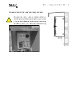
Page 8: ...LLATION OF THE CONTROL PANEL OUTSIDE Whenever the control panel is installed outdoors it must be placed under an appropriate cover to protect it from the direct incidence of rain and sun considering that 40ºC cannot be exceeded in the installation area ...

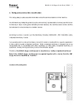
Page 9: ...inery Directive 2006 42 CE RD 1644 2008 partly completed machinery means an assembly which is almost machinery but which cannot in itself perform a specific application A drive system is partly completed machinery Partly completed machinery is intended only to be incorporated into or assembled with other machinery or other partly completed machinery or equipment thereby forming machinery to which ...

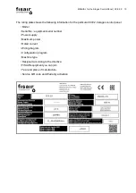
Page 10: ...particular CCE2 0 stages control panel Model Serial No equipment serial number Power supply Maximum power Rated current Wiring diagram Configuration program Machine type Designed according to the directive FISAIR equipment you can join Year and place of manufacture Service QR code and Warranty activation ...

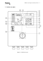
Page 11: ...MANUAL for the Stages Control Panel CCE2 0 11 5 Hardware description Figure 3 1 CCE2 0 front cover ...

Page 12: ...MANUAL for the Stages Control Panel CCE2 0 12 Figure 3 1 CCE2 0 front cover Figure 3 2 SEF 028 1 and SEF 032 1 v2 Power cards ...

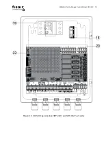
Page 13: ...MANUAL for the Stages Control Panel CCE2 0 13 Figure 3 3 CCE2 0 Open location SEF 028 1 and SEF 032 1 v2 cards ...

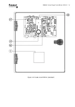
Page 14: ...MANUAL for the Stages Control Panel CCE2 0 14 Figure 3 4 Inside cover CCE2 0 standard ...

Page 15: ...MANUAL for the Stages Control Panel CCE2 0 15 Figure 3 5 Inside cover CCE2 0 optional data bus and conductivity cards IP Connection ...

Page 16: ...MANUAL for the Stages Control Panel CCE2 0 16 Figure 3 6 Inside cover CCE2 0 optional data bus and conductivity cards RTU Connection ...

Page 17: ...F 027 1 Art Cod 52300012 3 LED Yellow Live equipment 4 LED Red General fault 5 Operating key in Manual mode 6 Start stop status change button 7 Operating key in Automatic mode 8 OK button ENTER 9 Back button ESC 10 Navigation keys 11 LED Blue UV Lamp is operating 12 LED Yellow Indicates the water supply solenoid valve is powered 13 LED Green Indicates the drain valve motor is powered 14 LED Green ...

Page 18: ...pump running Red Malfunction 17 Display screen 18 Power terminals X1 19 Magneto thermal circuit breaker U1 in electrical diagram to protect water pump Art Cod 64350010 55 W single phase pump Art Cod 64350010 60 W 3 phase pump Art Cod 64350005 90 W single phase pump Art Cod 64350004 125 W 3 phase pump Art Cod 64350005 240W 3 phase pump Art Cod 64350020 370W single phase pump 20 Electronic power car...

Page 19: ... 64600012 24 Fuse F3 to protect the water supply solenoid valve Art Cod 64600012 25 Fuse F4 for drain emptying motor valve protection Art Cod 64600012 26 Fuse F5 for UV lamp protection Art Cod 64600013 27 Relay RL1 for water recirculation pump Art Cod 64130019 28 Relay RL2 for UV lamp Art Cod 64130018 21 Relay RL3 for water supply solenoid valve Art Cod 64130018 30 Central processing card SEF 025 ...

Page 20: ...ee location in chapter 4 34 Conductivity probe with 2 m cable for CCE2 0 C optional Art Cod 64220250 35 Conductivity sensor card SEF 026 for CCE2 0 C optional Art Cod 52300011 36 1 Communication card via data bus Modbus TCP IP 2 0 optional SEF 029 Art Cod 52300014 Communication card SEF 031 via data bus BACnet IP 2 0 optional Art Cod 52300014 36 2 Communication card SEF 030 via data bus Modbus RTU...

Page 21: ...Function and Article Code 37 Stage processing card MPCB IN01 Analog signal for stages 0 10V or 4 20mA Code Art 52300018 40 24 VDC Power supply 41 10 pins Flat cable connector J21 Between SEF 028 1 and SEF 032 42 Fuse of stage n Fn n 1 2 3 4 5 43 Relay of stage n Rln n 1 2 3 4 5 Rln ...

Page 22: ...Power Max Voltage Optional 24VDC J12 Water drain emptying motor valve supply 5W 24Vdc Mandatory J13 Water supply solenoid valve 50W 24Vdc Mandatory J14 Water drain emptying motor valve 40W 24Vdc Mandatory J15 Emptying motor valve feedback position limit switch opened Not powered Mandatory J16 Maximum water level sensor NC contact Not powered Mandatory J17 Minimum water level sensor NO contact Not ...

Page 23: ...omatic mode Not powered J22 Not used 500VA 250V Optional J23 Remote fault signal 500VA 250V Optional J24 Remote operation signal 500VA 250V Optional J25 Remote voltage signal 500VA 250V Optional J10 UV lamp supply 40W 230V Mandatory J11 Water recirculation pump 240W to 400 V 370W to 230 V Connection of drain emptying valve actuators NO COM SEF 028 1 connection Actuator Actuator wire number code Ac...

Page 24: ...mA A Regulated analog signal of stage control 0 10 VDC Connect this signal to Jumper 1 J1 Connect Jumper JH1 JH2 and JH3 in position 1 2 B Regulated analog signal of stage control 4 20 mA Connect this signal to Jumper 2 J2 Connect jumper JH4 in position 1 2 and Jumper JH5 and JH6 in position 2 3 When the data bus communication options are available the analogue signal regulation card MPCB IN01 mus...

Page 25: ...rent stages to the SEF 032 card according to figure 4 4 Figure 4 4 SEF 32 Card Detail of the connection Solenoid valves Connection for each irrigation stage Rojo red Negro black Ground Connect No of cassette irrigation solenoid valve connections according to the number of stages available ...

Page 26: ...ct the conductivity probe to the SEF 026 card and the cables according to the indicated colours earth to J3 either of the two interlocks Figure 4 5 SEF 026 Card 5 Optional Modbus RTU communication Connect the 3 cables identified with X A and B on the SEF 030 1 card Figure 4 6 SEF 030 1 Card BLACK J3 ...

Page 27: ...as inductive loads electric motors solenoid coils welding machinery or fluorescent light circuits The electrical noise or interference generated from these sources and the effect on controllers is difficult to define but the most common symptoms are erratic control or intermittent operational problems Important For maximum EMC effectiveness wire all humidity high limit and airflow controls using m...

Page 28: ...anual MAN or automatic AUTO MAN Select manual mode MAN from the command and display to enter that mode The following information is shown on the Display through 3 screens that alternate continuously Screen 1 Name of the Company FISAIR S L U Status indication HEF2E ON MAN Screen 2 Date 01 01 2019 Time 21 00 Conductivity value and water temperature μS cm In the case of having conductivity control Sc...

Page 29: ...sly Screen 1 Name of the Company FISAIR S L U Status indication HEF2E ON AUTO Screen 2 Date 01 01 2019 Time 21 00 Conductivity value and water temperature μS cm In the case of having conductivity control Screen 2 Analog input value 0 10V The analog input value can appear at 4 20mA No of active stages S1 S2 S3 If there is a fault an alarm code is shown on the second line of the display see section ...

Page 30: ... another using the vertical arrows Use the right arrow to advance to the next level within a screen and the left arrow to go back a level The two possible configurations are shown below 8 1 Emptying Emptying the basin is configured using the following control options 8 1 1 Emptying by conductivity control Partial emptying by the conductivity sensor is controlled by the Set point and the following ...

Page 31: ...VER Max 24h While the equipment is running it is fully emptied periodically according to the time value set in T05 Timer T06 min 0 h Max 24h The delay time for complete emptying is set according to the time value in T06 with the equipment switched off 8 1 3 No emptying never The basin is never emptied These Timers are configured in chapter Settings ...

Page 32: ...acturing process from the panel During the pre start up cycle the duct fans for the air to be treated must be turned off The UV lamp must not be switched on during this process Once this function is enabled the equipment must be started at the Manual mode MAN to proceed with the start up cycles The following control options are available Enabled Enables the start up process Disabled Enables the st...

Page 33: ... available stages Analog signal range VDC No Active solenoid valves Analog signal range mA No Active solenoid valves 5 Stages 0 0 2 VDC All OFF 4 2 mA All OFF 0 3 2 VDC S1 4 3 7 2 mA S1 2 1 4 VDC S1 S2 7 3 10 4 mA S1 S2 4 1 6 VDC S1 S2 S3 10 5 13 6 mA S1 S2 S3 6 1 8 VDC S1 S2 S3 S4 13 7 16 8 mA S1 S2 S3 S4 8 1 10 VDC S1 S2 S3 S4 S5 16 9 20 mA S1 S2 S3 S4 S5 4 Stages 0 0 2 VDC All OFF 4 2 mA All OF...

Page 34: ... 1 If the UV lamp is installed immersed in the basin a bridge must be made in J18 IN1 Note 2 Each time the UV lamp is switched on an internal 12 000 hr operating counter is activated only when the equipment is running After these 12 000 hours of operation the A51 error is triggered to replace the lamp Note 3 After the lamp is replaced following an A51 error the 12 000 hour counter must be reset by...

Page 35: ...the same network each should have a different value Fallback Ip Adrr Used to enter the address manually if there is no DHCP server in the network It assumes that the mask is always 255 255 255 0 and that the network Gateway is the same as that entered ending in 1 For example if you enter 192 168 1 23 the gateway will be 192 168 1 1 IP test Shows the current IP address to be assigned by the server ...

Page 36: ... control 1066 Write pre set on configuration 0 Disabled 1 Enabled 1068 Write pre set on cycle configuration Write range 0 10 cycles 1070 Write Language 0 Spanish 1 English 2 German 3 French Address Description Writing range increase Factory setting 1012 Write conductivity Set Point 0 1999µS cm increase 1µS cm 300 µS cm 1030 Write Timer T01 30 1000s increase 15s 90s 1032 Write Timer T02 1 15 min in...

Page 37: ...06 0 24h 1h 2042 Read Timer T07 5 360s 30s 2044 Read Timer T08 10 60min 15min These values are shown in seconds Address Description Reading 2116 Read equipment live J25 0 not live yellow led 3 Off 1 live yellow led 3 On 2118 Read general equipment failure J23 0 no equipment failure red led 4 Off 1 equipment failure red led 4 On 2120 Read general equipment operation status J24 0 not working 1 in op...

Page 38: ...ircuit breaker correct 2136 UV lamp operating status sensor J18 0 No fault 1 Fault 2138 Sample active stages 0 0 active stages 1 1 active stages 2 2 active stages 3 3 active stages 4 4 active stages 2200 Alarm shows the equipment alarm code 0 NO ALARM 1 CPU 2 CLOCK 4 PROBE 8 LEVEL SENSORS 16 CIRCUIT BREAK FAULT 32 UV FAULT 64 DRAIN 128 FILLING 256 MOTOR VALVE 1 512 DIRTY WATER 1024 AUXILIARY FAULT...

Page 39: ...n of each communication object Object Description Writing SET OnOff Auto Analog_Output 0 1010 Write position disconnector switch I1 0 OFF 1 ON 2 AUTO Subject to interlocking function in J21 SET V CONTROL Analog_Output 12 1060 Write analogue signal 0 10 VDC step control Write range 0 10 SET V OR mA Analaog_Output 11 1061 Select if the steps are regulated by Volts 0 V or amperes 1 A SET mA CONTROL A...

Page 40: ... increase 1h 0min never SET Timer 6 Analog_Output 6 1040 Write Timer T06 0 24h increase 1h 1h SET Timer 7 Analog_Output 7 1042 Write Timer T07 5 360s increase 5s 30s SET Timer 8 Analog_Output 8 1044 Write Timer T08 10 60min increase 5min 15min These objects are bidirectional In addition to working as writing they show the reading of their states Read The following table shows the read function of ...

Page 41: ...UV lamp operation status J10 0 Off blue led 11 Off 1 On blue led 11 On 2 Fault blue led 11 flashing GET STATUS J13 Analog_Input 8 2124 Read filling solenoid valve status J13 0 Off yellow led 12 Off 1 On yellow led 12 On GET STATUS J14 Analog_Input 9 2126 Read drainage motor valve power status J14 0 No power green led 13 Off 1 Powered green led 13 On GET STATUS J15 Analog_Input 10 2128 Read drain m...

Page 42: ... Motor pump circuit breaker status 0 Circuit breaker fault 1 Circuit breaker correct GET STATUS J18 Analog_Input 14 2136 UV lamp operating status sensor J18 0 No fault 1 Fault GET ALARMS Analog_Input 15 2200 Alarm shows the equipment alarm code 0 NO ALARM 1 CPU 2 CLOCK 4 PROBE 8 LEVEL SENSORS 16 CIRCUIT BREAK FAULT 32 UV FAULT 64 DRAIN 128 FILLING 256 MOTOR VALVE 1 512 DIRTY WATER 1024 AUXILIARY F...

Page 43: ...CCE2 0 43 8 7 Language Select the language you want from the Display Español English Deutsch Francais 8 8 Date Set the exact date and time by entering the data shown on the following screens Seconds Minutes Time Day of the week Month Year ...

Page 44: ... level 9 1 SET POINT µS cm if applicable Enter the conductivity set point If this conductivity value is exceeded the motorised drain valve is activated and the water is renewed to the desired conductivity lower than the Set point It must be remembered that the TIMER T07 regulates the time for the set point value to be exceeded before opening the drain valve while TIMER T02 established the time bet...

Page 45: ...evel sensor to confirm the minimum water level or obstruction of the drain after the emptying command The Timer range is from 1 min to 60 min The factory set value is 10 min 9 5 TIMER T04 ex SW2 CD Enter the additional complete emptying time during which the emptying motor valve will be open The Timer range is from 30 min to 400 min The factory set value is 60 min 9 6 TIMER T05 ex SW3 AB Enter the...

Page 46: ...is switched off 9 8 TIMER T07 ex SW4 CD Enter the set point time before partial emptying by opening the drain motor valve due to the conductivity being continuously exceeded The Timer range is from 5 s to 360 s The factory set value is 30 s 9 9 TIMER T08 Enter the maximum time for the filling to occur Time for the minimum level to be reached once the basin is on process of filling The Timer range ...

Page 47: ...conductivity IV Obtain the liquid temperature e g 22ºC shown in the supervision menu Wait 5 min until the temperature reading stabilises V Check the solution conductivity at that temperature on the table on the bottle label e g 1332 µS VI This value is entered in the menu CALIBRATION HIGH To do this access the menu containing the conductivity value for the measuring probe e g 1380 µS Correct it ac...

Page 48: ...n 0 to 1 The LEDs over the control and display interface are swept and the low voltage remote signalling contact is activated Connection J25 3 The initial adjustments configuration and settings to the working mode choice are made a UV lamp if applicable Turn the UV lamp on or off using the navigation buttons See section 6 3 b Conductivity probe if applicable Adjusting the SET POINT The conductivit...

Page 49: ...ill open and the water in the basin will be renewed due to the filling solenoid valve staying open the filling solenoid valve is controlled and closes only when the maximum level is detected A minimum partial emptying of 100s will be performed the motor valve will be closed and the basin filled until the float valve cuts out The filling solenoid valve will remain open the closing of the filling so...

Page 50: ...at best suits your needs automatic or manual The desired working mode is selected using the MAN or AUTO buttons Remember to have the I1 disconnector in position 1 See section 5 Supervision to display the equipment status MAN AUTO or START MAN START OPERATION AUTO START OPERATION ...

Page 51: ...is a fault in the mechanical float valve the basin continues filling until the level sensor detects the maximum water level LED turns red III Once the minimum water level has been reached green LED the water recirculation pump turns on green LED after the time established in TIMER TO1 IV During operation or after switching off the LEDs will light up depending on the emptying settings V During the ...

Page 52: ...or signal 46 Drain emptying motor valve Emptying confirmation time has elapsed no minimum level of water detected Check proper operation of the emptying motor valve 47 Water supply Fill confirmation time has elapsed no minimum level of water detected Check proper operation of the water supply solenoid valve 48 Drain emptying motor valve Established time has elapsed without detecting feedback from ...

Page 53: ...MANUAL for the Stages Control Panel CCE2 0 53 13 Declaration of conformity 13 1 D C Machine ...

Page 54: ...MANUAL for the Stages Control Panel CCE2 0 54 13 2 D C Partly completed machinery ...

Page 55: ...MANUAL for the Stages Control Panel CCE2 0 55 14 Warranty ...

Page 56: ...MANUAL for the Stages Control Panel CCE2 0 56 ...

Page 57: ...IÓN F ...

Page 58: ...IÓN ...

Page 59: ...IÓN MAN P Ev1 Mv1 P P ...

Page 60: ...F IÓN ...

Page 61: ...IÓN ...

Page 62: ...IÓN MAN P Ev1 Mv1 P P ...

Reviews: