DFLEX Assembly instructions |
20
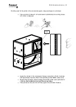
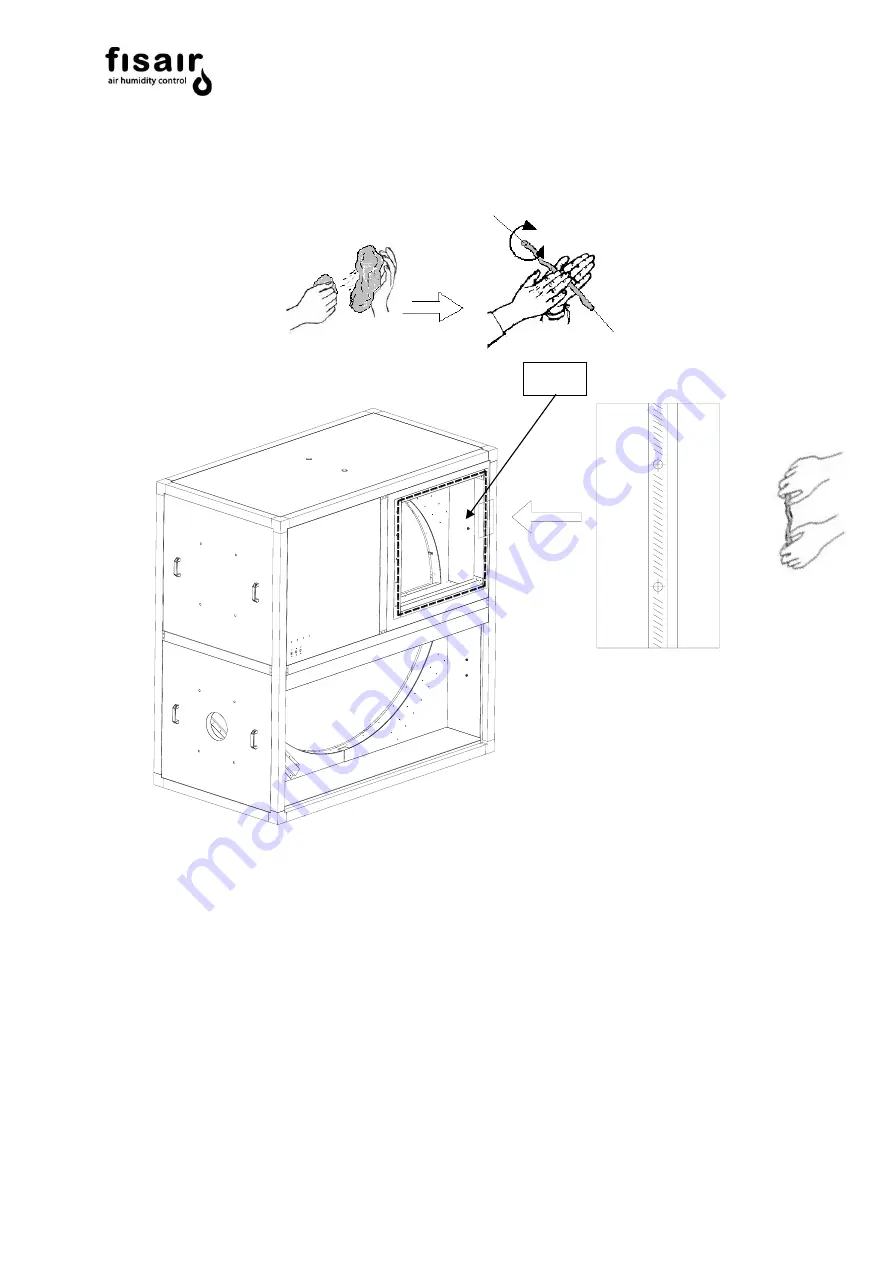
Find the putty for the joints in the accessories pack, shape and apply it as follows:
•
Take a portion of about 4 cm³ and knead it cylindrically into a string shape
of 7-9 mm in diameter.
•
Apply the
‘string’ in the rectangular flange connection of both modules,
and specifically in section S5-4 corresponding to the MOD4 (basic unit).
•
Repeat this operation until the flange around the entire outer perimeter is
complete.
Be careful not to cover the screw holes.
•
This process is the same for all three types of reactivation heaters.
S5-4
Summary of Contents for DFLEX 1100
Page 2: ...DFLEX Assembly instructions 2...
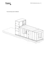
Page 16: ...DFLEX Assembly instructions 16 The following result is obtained...
Page 29: ...DFLEX Assembly instructions 29 DFLEX 1100 400V 5...
Page 30: ...DFLEX Assembly instructions 30 DFLEX 1100 440 480V NOT WIRING...
Page 31: ...DFLEX Assembly instructions 31 DFLEX 1300 400V 5...
Page 32: ...DFLEX Assembly instructions 32 DFLEX 1300 460V 5 NOT WIRING...
Page 33: ...DFLEX Assembly instructions 33 DFLEX 1700 400V 5...
Page 34: ...DFLEX Assembly instructions 34 DFLEX 2100 400V 5...
Page 35: ...DFLEX Assembly instructions 35 DFLEX 2100 460V 5 48 Elementos NOT WIRING...
Page 36: ...DFLEX Assembly instructions 36 DFLEX 2100 460V 5 45 elements Requires SSR in E4 NOT WIRING...


