DFLEX Assembly instructions |
28
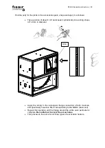
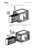
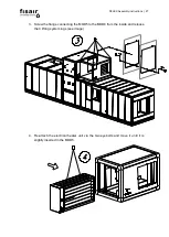
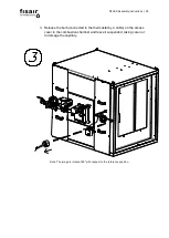
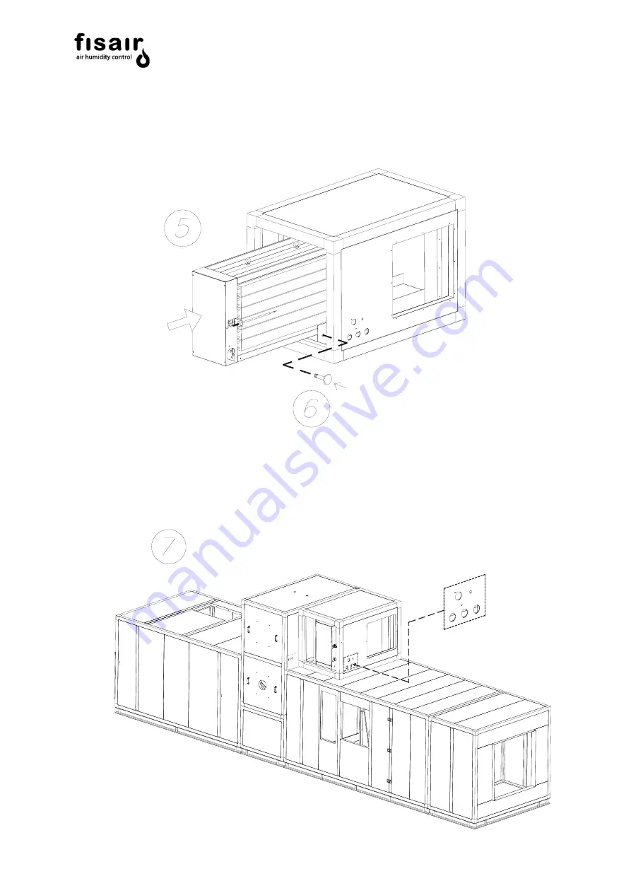
5. Release the eyebolts from the electrical heater and insert it completely inside by
sliding until the fixing holes overlap.
6. Replace the screw fixing the electric heater cartridge to the support mouth.
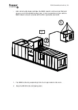
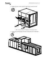
7. Once the electrical heater unit is inserted and attached, the electrical connection
must be made. This is done by inserting the installed wiring in the MOD3 so that
it passes through the wall bushings and the electrical unit hole into the heater unit
connection box.
Summary of Contents for DFLEX 1100
Page 2: ...DFLEX Assembly instructions 2...
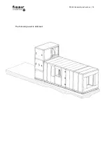
Page 16: ...DFLEX Assembly instructions 16 The following result is obtained...
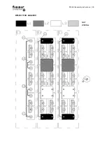
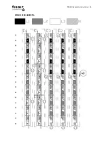
Page 29: ...DFLEX Assembly instructions 29 DFLEX 1100 400V 5...
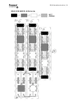
Page 30: ...DFLEX Assembly instructions 30 DFLEX 1100 440 480V NOT WIRING...
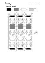
Page 31: ...DFLEX Assembly instructions 31 DFLEX 1300 400V 5...
Page 32: ...DFLEX Assembly instructions 32 DFLEX 1300 460V 5 NOT WIRING...
Page 33: ...DFLEX Assembly instructions 33 DFLEX 1700 400V 5...
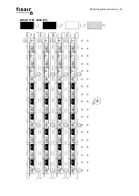
Page 34: ...DFLEX Assembly instructions 34 DFLEX 2100 400V 5...
Page 35: ...DFLEX Assembly instructions 35 DFLEX 2100 460V 5 48 Elementos NOT WIRING...
Page 36: ...DFLEX Assembly instructions 36 DFLEX 2100 460V 5 45 elements Requires SSR in E4 NOT WIRING...

