HEF2 Series MANUAL
15
6. MECHANICAL DESIGN, OPERATING PRINCIPLES AND COMPONENTS.
(Recirculated water, standard on/off)
MECHANICAL DESIGN
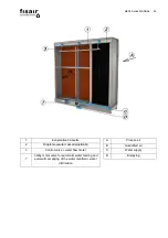
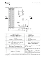
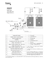
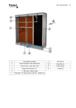
The humidifier comprises the following elements:
•
A stainless steel self-supporting chassis-water tank structure that houses the unit.
•
A set of evaporative cassettes of variable sizes and thicknesses, depending on the model and stainless
steel surround.
•
A stainless steel float valve automatic control mechanism for the water supply, to maintain the appropriate
level in the water tank, so the unit works correctly. This valve can be regulated in order to set it to the
available water pressure in the network.
•
A stainless steel water tank to hold the water, which is designed so it can be completely emptied by gravity.
•
A pump for supplying water from the water tank to evaporative panels (technical data on chapter 9.2.c).
•
A stainless steel mechanism integrated into the water tank acting as an overflow for the system in the
event of water level control faults.
•
A distribution collector + regulation valves with flow meter set to supply the appropriate irrigation
individually to the evaporative panels.
•
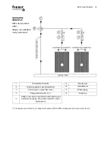
A diversion from the water flow to the distribution collector regulates a constant flow of water, which is
eliminated from the system in order to maintain a uniform amount of mineral salts
in the irrigation water, which we will refer to as the “Constant bleed-off system”.
(See page 36).
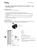
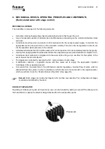
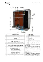
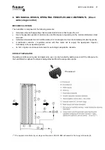
DROPLET SEPARATOR
Operating conditions giving rise to droplet carry-over, can be handled by adding a
second PP profile panel to the humidifiers to capture the droplets being detached
from the evaporative panel.
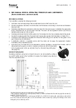
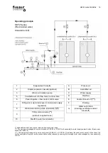
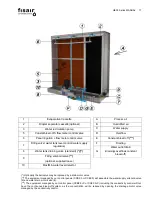
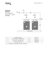
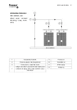
* Optionally the ball valve may be replaced by a drain motor valve.
**The equipment managed by our control panels (CCB2.0 or CCE2.0) will assemble the water supply solenoid valve (9)
and water drain motor valve (8*).
***The equipment managed by our control panel (CCB2.0+C or CCE2.0+C) including the conductivity control will not
have the continuous bleed-off system, as the concentration will be reduced by opening the drainage motor valve
managed by the conductivity control.
Process air
(***)
(*) (**)
(**)
Summary of Contents for HEF2 SERIES
Page 2: ...HEF2 Series MANUAL 2...
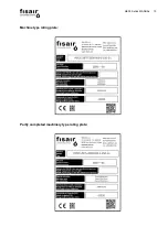
Page 13: ...HEF2 Series MANUAL 13 Machine type rating plate Partly completed machinery type rating plate...
Page 66: ...HEF2 Series MANUAL 66 Wiring Diagram connections Dimensions GDB13 1 GDB13 1...
Page 67: ...HEF2 Series MANUAL 67 Adjusting A B Auxiliary contacts...
Page 69: ...HEF2 Series MANUAL 69 Wiring Diagram connections Dimensions...
Page 70: ...HEF2 Series MANUAL 70 Manual positioning...
Page 76: ...HEF2 Series MANUAL 76 13 9 G Perimeter closures cover plates dimensional drawings...
Page 78: ...HEF2 Series MANUAL 78 Dimensional drawing for Top Cover Plates...
Page 98: ...HEF2 Series MANUAL 98 H1 ON OFF or BUS...
Page 101: ...HEF2 Series MANUAL 101 1 Cassette ON 2 Cassettes ON 3 Cassettes ON Ideal Stage Control...
Page 102: ...HEF2 Series MANUAL 102 Control by stages or control ON OFF...
Page 103: ...HEF2 Series MANUAL 103 H1 ON OFF 0 10Vcc regulated or BUS...
Page 105: ...HEF2 Series MANUAL 105 Dew point control Dew point control...
Page 106: ...HEF2 Series MANUAL 106 H1 ON OFF or BUS...
Page 117: ...HEF2 Series MANUAL 117...
Page 120: ...HEF2 Series MANUAL 120 Remove the PP R D25 piping to the header PP R D25 pipe...
Page 121: ...HEF2 Series MANUAL 121...
Page 122: ...HEF2 Series MANUAL 122...
Page 123: ...HEF2 Series MANUAL 123...
Page 125: ...HEF2 Series MANUAL 125...
Page 126: ...HEF2 Series MANUAL 126 23 CLEANING THE INDIVIDUAL IRRIGATION SYSTEM...
Page 127: ...HEF2 Series MANUAL 127...
Page 128: ...HEF2 Series MANUAL 128 24 LIST OF SPARE PARTS...


