HEF7 series manual 20
PUMP TECHNICAL DATA
10. Level detector connection
1. Minimum level detector (low level S1):
Level detector must be connected to protect the water pump
working. Water level in basin is detected by this level detector (J17
sensor indicates minimum water level NO, take a look on CCB2.0
manual).
2. Maximum level detector (high level S2):
The maximum level is used as a security system in a float valve
regulation water feed possible failure event. It must not be used to
regulate the fresh water inlet.
I
n case the equipment has a filling
solenoid valve, connect it to this level so that it is cut for safety
(J16 sensor indicates maximum water level NC, take a look on
CCB2.0 manual).
Remark:
Max Voltage: 175 Vcc / 110 Vca
Max Current: 1 Acc
Temperature: -20...120ºC
Min. Density: 0, 75 gr/cm
3
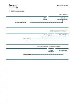
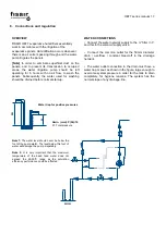
Figure 1:
Explanatory diagram to confirm which components are
managed by levels S1 and S2.
It’s not a
unifilar
diagram
.
Electrical power supply
Service voltage (Vac)
230
Frequency (Hz)
50
Motor nominal power (W)
370
Consumption (A)
2,1
Degree of protection
Degree of protection according to
EN 60529
IP 68
Enviromental conditions
Max. fluid temperature (ºC)
35
Functional data
Max working height (m)
7
Max. working flow (m3/h)
10
N.C. = normally closed ALTO= High level S2
N.A. = normally open BAJO= Low level S1
C= Common
Example connection to CCB2.0
Not
Co
n
n
e
c
te
d
C
-S2
C
-S1
Summary of Contents for HEF7 Series
Page 2: ...HEF7 series manual 2...
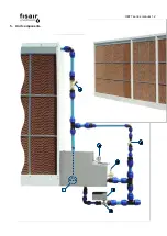
Page 12: ...HEF7 series manual 12 5 Unit components 1 2 4 3 7 5 6...
Page 34: ...17 Machine conformity declaration...
Page 35: ...18 Cuasi machine conformity declaration...
Page 36: ...19 WARRANTY...
Page 37: ......

