HEF7 series manual 25
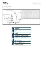
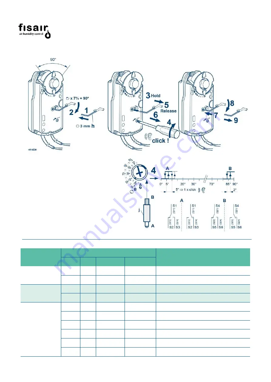
Manual positioning
Position Block Unblock
Adjusting: A, B Auxiliary contacts
Factory
setting
A= 5º
b= 85º
Cable labeling
Pin
Cable
Meaning
Code
No.
Color
Abbrev.
Actuators
AC 24 V
DC 24…48 V
G
1
red
RD
System potential AC 24 V/DC 24…48 V
G0
2
black
BK
System neutral
Actuators
AC 230 V
L
3
brown
BN
Phase AC 230 V
N
4
blue
BU
Neutral conductor
Auxiliary switch
Q11
S1
grey/red
GY RD
Switch A input
Q12
S2
grey/blue
GY BU
Switch A normally-closed contact
Q14
S3
grey/pink
GY PK
Switch A normally-open contact
Q21
S4
black/red
BK RD
Switch B input
Q22
S5
black/blue
BK BU
Switch B normally-closed contact
Q24
S6
black/pink
BK PK
Switch B normally-open contact
Summary of Contents for HEF7 Series
Page 2: ...HEF7 series manual 2...
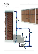
Page 12: ...HEF7 series manual 12 5 Unit components 1 2 4 3 7 5 6...
Page 34: ...17 Machine conformity declaration...
Page 35: ...18 Cuasi machine conformity declaration...
Page 36: ...19 WARRANTY...
Page 37: ......

