background image

Panda_4800i PMS_eng.R04

14.2.13

Fischer Panda GmbH

Manual

Panda 4800i PMS

230 V - 50 Hz / 3,8 kW 

Super silent technology

Summary of Contents for Panda 4800i PMS

Page 1: ...Panda_4800i PMS_eng R04 14 2 13 Fischer Panda GmbH Manual Panda 4800i PMS 230 V 50 Hz 3 8 kW Super silent technology ...

Page 2: ...serves all rights regarding text and graphics Details are given to the best of our knowledge No liability is accepted for correctness Technical modifications for improving the product without previous notice may be undertaken without notice Before installation it must be ensured that the pictures diagrams and related material are applicable to the genset supplied Enquiries must be made in case of ...

Page 3: ... 1 6 1 Special instructions and hazards of generators 20 1 6 1 1 Protective conductor and potential equalisation 21 1 6 1 2 Protective conductor for Panda AC generators 21 1 6 1 3 Switch off all loads while working on the generator 21 1 6 1 4 Potential equalisation for Panda AGT DC generators 21 1 6 1 5 Safety instructions concerning cables 22 1 6 2 Recommended starter battery sizes 22 1 6 3 Impor...

Page 4: ...i PMS 39 4 2 3 Front View 4800i PMS 40 4 2 3 1 Front connections 4800i PMS 41 4 2 4 Back View 4800i PMS 42 4 2 5 View from above 4800i PMS 43 4 3 Details of Functional Units 44 4 3 1 The Panda iControl2 panel 44 4 3 1 1 Components of Cooling System Raw water 4800i 45 4 3 2 Components of combustion air 4800i PMS 46 4 3 3 Components of the Fuel System 4800i PMS 47 4 3 4 Electrical Connection 4800i P...

Page 5: ...g items need to be installed 81 5 8 2 Connection of the fuel lines at the tank 84 5 8 3 Position of the pre filter with water separator 85 5 9 Electrical Connection 4800i PMS 86 5 10 Generator DC system installation 87 5 10 1 Connection of the 12V starter battery 87 5 10 2 How to connect two 12V batteries to a 24V battery bank 90 5 10 3 Relays and DC fuse 91 5 10 4 Connection of the remote control...

Page 6: ...ter a medium term standstill 3 to 6 months 116 6 17 4 Arrangements at a long term standstill shutdown 117 6 17 4 1 Arrangements for conservation 117 6 17 4 2 Arrangements after a long term standstill shutdown recommissioning more than 6 months 118 7 Generator Failure 119 7 1 Personal requirements 119 7 2 Safety instructions for this chapter 119 7 3 Tools and measuring instruments 121 7 4 Overloadi...

Page 7: ...ecting and saving a unit for the temperature value output 147 3 Installation 149 3 1 Personnel 149 3 1 1 Hazard warnings for installation 149 3 2 Disposal of the components 150 3 2 1 Panda iControl2 panel with installation housing 150 3 2 2 Terminal assignments on the Panda iControl2 panel 151 3 3 Dimensions 152 3 4 Wiring of the Panda iControl2 controller 153 3 4 1 Terminal assignments on the Pan...

Page 8: ...171 7 5 1 1 Uninterrupted AC power UPS function 171 7 5 1 2 Dynamic current limiter 171 7 5 2 Settings in the Victron VE Configure II Software Inverter 172 7 5 2 1 Assist current boost factor 172 7 6 Operation manual 173 7 6 1 Primary remarks Winter operation 173 7 6 2 Load at the PMGi 173 7 6 3 Automatic start 173 7 7 Status LED s 173 7 8 Cooling of the PMGi 173 7 9 Installation of the PMGi 174 7...

Page 9: ...t Fischer Panda can supply Service Kits which are ideal for regular servicing tasks We only supply the highest quality components which are guaranteed to be the RIGHT parts for your generator Service Plus Kits are also available and ideal for longer trips where more than one service interval may be required If you require assistance please contact your Fischer Panda Dealer Please do not attempt to...

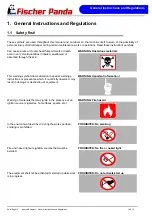
Page 10: ...all quantities if inhaled swallowed or absorbed through the skin WARNING Important information This warning symbol draws attention to special warnings instructions or procedures which if not strictly observed may result in damage or destruction of equipment WARNING Fire hazard Warning of materials that may ignite in the presence of an ignition source cigarettes hot surfaces sparks etc PROHIBITED N...

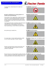
Page 11: ... to the danger of electric shock and draws attention to special warnings instructions or procedures which if not strictly observed may result in severe personal injury or loss of life due to electric shock WARNING General warning General warning of a hazard area WARNING Danger due to inhalation and or ingestion Can cause acute or chronic health impairments or death even in very small quantities if...

Page 12: ...ger due to corrosive substances potential contamination of person Warning of substances that cause chemical burns upon contact These substances can act as contaminants if introduced into the body WARNING System may be pressurised When the system is opened the pressure can be relieved abruptly and expel hot gases and fluids Risk of injury due to parts flying about burn hazard due to liquids and gas...

Page 13: ...gles PPE Wearing safety goggles protects the eyes from damage Optical spectacles are not a replacement for the corresponding safety goggles MANDATORY INSTRUCTION Wear protective gloves PPE Wearing protective gloves provides the hands from hazards like friction graze punctures or deep cuts and protects them from contact with hot surfaces MANDATORY INSTRUCTION Observe the instructions in the manual ...

Page 14: ...mbols are used throughout this manual to show which tool must be used for maintenance or installation Spanners W A F X width across flats of X mm Hook wrench for oil filter Screw driver for slotted head screws and for Phillips head screws Multimeter multimeter with capacitor measuring unit Socket wrench set Hexagon socket wrench set ...

Page 15: ...neral Instructions and Regulations 14 2 13 Kapitel Chapter 1 General Instructions and Regulations Seite Page 15 Clamp on ammeter DC for synchronous generators AC for asynchronous generators Torque wrench ...

Page 16: ...hese measures lies with those who undertake the installation of the generator in the final system 1 4 Customer registration and guarantee Use the advantages of registering your product you will receive a Guarantee Certificate after approval of your installation data you will receive extended product information that may be relevant to safety You will receive free upgrades as necessary Additional a...

Page 17: ...ices and ensure work safety Familiarise yourself with the equipment and its limits Keep the generator in good condition 1 5 3 Personal protective clothing PPE For maintenance and repair work on the equipment do not wear loose torn or ill fitting clothing that may catch on protruding parts or come into contact with pulleys cooling disks or other rotating parts which can cause severe injury Wear app...

Page 18: ...ust fumes are vented appropriately leak proof system and that an adequate fresh air supply is available for the generator and the operator forced ventilation Check the system regularly for leakage and eliminate leaks as applicable Exhaust gases and parts containing such fumes are very hot they may cause burns under certain circumstances Always keep flammable parts away from the generator and the e...

Page 19: ...y from the batteries Ensure that the battery terminals are tightly connected and not corroded to avoid sparking Use an appropriate terminal grease Check the charge level with an adequate voltmeter or acid siphon Contact of a metal object across the terminals will result in short circuiting battery damage and high explosion risk Do not charge frozen batteries Heat the batteries to 16 C 61 F prior t...

Page 20: ...th water and soap and dry them with a soft cloth Immediately replace damaged or missing warning and instruction signs This also applies to the installation of spare parts 1 6 1 Special instructions and hazards of generators The electrical installations may only be carried out by trained and qualified personnel The generator must not be operated with the cover removed If the generator is being inst...

Page 21: ...g The battery must always be disconnected if work on the generator or electrical system is to be carried out so that the generator cannot be started up unintentionally 1 6 1 3 Switch off all loads while working on the generator All loads must be disconnected prior to working on the generator to avoid damage to the devices In addition the semiconductor relays in the AC control box must be disconnec...

Page 22: ... is installed free from any influence due to friction and crushing 1 6 2 Recommended starter battery sizes Use only batteries approved by the manufacturer as starter batteries Use the battery capacity recommended by the engine manufacturer 1 6 3 Important instructions for batteries starter and or traction batteries ATTENTION Start up Installation of battery connection lines Observe the instruction...

Page 23: ...nda generator capsule the positive battery cable must be routed so that it is protected from heat and vibrations by means of an adequate conduit protective sleeve It must be installed so that it does not come into contact with rotating parts or such that heat up during operation such as pulley exhaust manifold exhaust pipe and motor itself Do not overtighten the cable as it may be damaged otherwis...

Page 24: ...a risk of skin burns Protect all battery contacts against accidental contact For battery banks Use only deep cycle batteries Starter batteries are not suitable Lead acid gel batteries are recommended They are maintenance free cycle stable and do not release gases Never charge a frozen battery Avoid battery short circuits Ensure proper ventilation of the battery to vent gases that may be released B...

Page 25: ... by electrical shocks 5 Safety steps to follow if someone is the victim of electrical shock Do not touch the injured person while the generator is running Switch off the generator immediately If you cannot switch off the generator pull push or lift the person to safety using a wooden pole rope or some nonconducting material Call an emergency doctor as soon as possible Immediately start necessary f...

Page 26: ...ds you by pulling slowly 4 Open Airway Tilt head back and lift chin Shout Are you OK 5 Check for Breathing Look listen and feel for breathing for 3 to 5 seconds 6 Give 2 Full Breaths Keep head tilted back Pinch nose shut Seal your lips tight around victim s mouth Give 2 full breaths for 1 to 1 seconds each 7 Check for Pulse at side of Neck Feel for pulse for 5 to 10 seconds 8 Phone EMS for Help Se...

Page 27: ...cted 3 2 Purpose of the manual and description of the definitions of the trained persons operators users This manual contains the working instructions and operating guidelines for the owner and user of Fischer Panda generators The manual is the base and the guideline for the correct installation and maintenance of Fischer Panda generators It does not substitute the technical evaluation and should ...

Page 28: ...y instructions are respected The user must be instructed by the operator regarding his activity at the generator espe cially concerning the maintenance 3 3 Components of the i system Fig 3 3 1 Panda i generator 1 Panda i PMS Generator Permanent Magnet Generator representative picture Fig 3 3 2 iControl panel 2 Panel Panda iControl with electronic board at the genera tor representative picture Fig ...

Page 29: ...it diagram representative picture 3 4 Range of operation Reliable power supply on sailing boats 3 5 Panda transport box 3 5 1 Bolted Fischer Panda transport box 1 Remove the bolts for cover sidewalls 2 Remove the cover 3 Remove the loose accessories 4 Remove the bolts for sidewalls floor pallet 5 Remove the sidewalls 6 Open the generator attachment 3 5 2 Fischer Panda transport box with metal tab ...

Page 30: ...3 6 1 Sound insulation capsule side part To open the sound insulation capsule the closures must be rotated roughly 180 counter clockwise Use a flat head screwdriver Pull the sidewalls out by gripping into the slots Fig 3 6 2 Closure locked Closure locked Fig 3 6 3 Closure open Closure open 3 6 1 Opening the GFK sound insulation capsule ...

Page 31: ...r transport For transport the Fischer Panda transport box shall be used for the generator The generator shall be securely at tached to the bottom of the box For loading unloading an adequate industrial truck shall be used Depending on the transport distance e g air cargo the generator fluids coolant engine oil fuel may have to be drained The corresponding instructions and warnings must be fitted t...

Page 32: ...on starter battery Starter batteries Self discharge of batteries is a physical and chemical pro cess and cannot be avoided even if the battery is disconnec ted For extended downtimes the battery shall be disconnected from the genset Charge battery regularly Observe instructions of the battery manufacturer Depending on the battery type check the acid level before charging and refill each cell up to...

Page 33: ...res for medium term downtimes hibernation Medium term downtimes 3 to 6 months 3 8 3 1 Courses for preservation Check battery charge status and recharge regularly roughly every 2 months as necessary Observe instructions of the battery manufacturer Check cooling water anti freeze level and refill as necessary The anti freeze agent must not be older than 2 years The anti freeze content shall be betwe...

Page 34: ...switch Hold stop lever on generator motor in neutral position and crank starter for approx 10 seconds Then pause for 10 seconds Repeat this procedure 2 times Perform visual check of the generator similar to initial commissioning and start up generator 3 8 4 Measures for extended downtimes decommissioning Downtimes more than 6 months 3 8 4 1 Courses for preservation Check battery charge status and ...

Page 35: ...and supplemented as necessary Attention Before recommissioning remove preservatives and pro tective measures 3 8 4 2 Measures for removing surface protection after extended downtimes recommis sioning over 6 months Check battery charge status and recharge if necessary Observe instructions of the battery manufacturer Check cooling water anti freeze level and cooling water level and refill as necessa...

Page 36: ...Seite Page 36 Panda_5000i_PVMV N_Book_eng R02 14 2 13 Leere Seite Intentionally blank Basics ...

Page 37: ...13 Panda_4800i PMS_eng R04 Kapitel Chapter 4 The Panda Generator Seite Page 37 4 The Panda Generator 4 1 Type plate at the Generator Fig 4 1 1 Type plate at the generator Picture shows 4000s SC Fig 4 1 2 Description type plate ...

Page 38: ...4800i PMS Fig 4 2 1 1 Right side view 03 07 08 06 09 12 13 01 05 04 10 11 02 01 Cylinder head 02 Actuator 03 Mechanical fuel pump 04 Speed adjust lever 05 Fresh water pump 06 Sound cover base part 07 Generator housing with coil 08 Combustion air intake 09 Cooling water out at winding 10 Heat exchanger 11 Starter motor 12 Generator air filter housing 13 Air suction hose ...

Page 39: ...1 Left side view 01 02 07 03 04 05 11 06 10 08 09 01 Starter motor 02 Solenoid switch for starter motor 03 Generator air filter housing 04 Fuse DC 05 Plug for optional electrical fuel pump inside box 06 Sound cover base part 07 Oil dipstick 08 Oil pressure switch 09 Thermo switch exhaust elbow 10 Fuel solenoid valve 11 Cylinder head valve cover ...

Page 40: ...apter 4 The Panda Generator 14 2 13 4 2 3 Front View 4800i PMS Fig 4 2 3 1 Front view 07 01 02 03 04 05 06 08 01 Cylinder head 02 Fuel solenoid valve 03 Ventilation screw solenoid valve 04 Fuel filter 05 Raw water pump 06 Fresh water pump 07 Fuel pump 08 Heat exchanger ...

Page 41: ...800i PMS 01 Passage exhaust hose 02 Cooling water in 03 Connection hose to external expansion tank 8mm 04 Connection hose from external expansion tank 10mm 05 Connection fuel OUT 06 Connection fuel IN 07 Oil drain hose 08 FP Bus cable to inverter 09 Cable for control panel 10 Load cable to inverter 11 Battery cable 12 Battery cable 13 Connection external ventilation valve ...

Page 42: ...0i PMS_eng R04 Kapitel Chapter 4 The Panda Generator 14 2 13 4 2 4 Back View 4800i PMS Fig 4 2 4 1 Back view 01 02 04 05 03 01 Starter motor 02 Generator power air filter housing 03 Air filter holder 04 Boxed i control 2 main board 05 Air inlet ...

Page 43: ...6 01 02 03 04 05 09 11 12 08 10 07 13 01 Generator power terminal box and air filter housing 02 Solenoid switch for starter motor 03 Injection nozzle 04 Water cooled exhaust elbow 05 Valve cover 06 Fuel solenoid valve 07 Fuel filter 08 Air suction hose 09 Starter motor 10 Cooling water connection block 11 Thermo sensor cylinder head 12 Fuel pump 13 Fresh water pump ...

Page 44: ...erves to pre sent the most important data of the system as well as warnings and error messages The control panel is equipped with four buttons for operating the Panda iControl2 controller Fig 4 3 1 Panda iControl 2 panel 1 On Off button Switching the Panda iControl2 controller on and off 2 Start Stop button Starting and stopping the generator confirming values in selection menus Enter key 3 Cursor...

Page 45: ...illing basin s up intake Up intake Down intake Exhaust with sea water outlet Sea water inlet Fresh water offtake to stilling basin s down intake 01 Cooling water in raw water in 02 Raw water pump 03 Connection hose for cooling circle ventilation valve 04 Oil cooler heat exchanger 05 Generator housing with coil 06 Cooling water in at engine 07 Water connection block cooling water out at engine 08 W...

Page 46: ...14 2 13 4 3 2 Components of combustion air 4800i PMS Fig 4 3 2 1 Combustion Air circle Z Inventor P 4 P 04 synchro FCB Obieg powietrza idw Air inlet Exhaust 01 02 03 04 05 01 Air inlet 02 Generator housing with coil 03 Generator air filter housing 04 Air in at engine 05 Water cooled exhaust elbow ...

Page 47: ...Generator Seite Page 47 4 3 3 Components of the Fuel System 4800i PMS Fig 4 3 3 1 Fuel circle nventor P 4 P 04 synchro FCB Obieg paliwa idw Fuel inlet Fuel outlet 01 02 03 04 05 01 Fuel in 02 Fuel pump 03 Fuel stop solenoid 04 Injection nozzle at engine 05 Fuel out Fuel return line ...

Page 48: ...04 Kapitel Chapter 4 The Panda Generator 14 2 13 4 3 4 Electrical Connection 4800i PMS Fig 4 3 4 1 Electrical Connection 4800i PMS Fig 4 3 4 2 01 Front Connections of the 4800i PMS 02 Starter battery 03 iControl 2 remote control panel 04 PMGi 5000 inverter ...

Page 49: ...at water cooled exhaust elbow This thermo switch is located at the water cooled exhaust elbow union and serves to monitor the temperature of the fresh water cooling system It takes a measurement at the hottest spot since the combustion gases are guided from the cylinder head for the exhaust elbow Fig 4 3 5 3 Thermo switch coil Thermo switch in the generator coil 1 Generator coil 2 Thermo switch 3 ...

Page 50: ...l filler neck with cap Normally the filler neck for the engine oil is on the top side of the valve cover A second filler neck is additionally attached at the operating side for numer ous generator types Please ensure that the filler necks are always well secured after filling with engine oil Consider also the references to the engine oil specification Fig 4 3 6 2 Engine oil dipstick Oil dipstick A...

Page 51: ...posed the oil change intervals are kept Fig 4 3 6 4 Engine oil drain hose Oil drain hose The Panda generator is so equipped that the engine oil can be drained by a drain hose The generator should always be installed in such a way that a collecting basin can be placed deep enough f this is not possible an electrical oil drain pump must be installed Note Lubricating oil should be drained in the warm...

Page 52: ...e on page 125 2 State of cooling water The external compensation tank should be filled up to a maximum during cold state It is very important that large expansion area remains above the cooling water level 3 Open sea cock for cooling water intake For safety reasons the sea cock must be closed after the generator has been switched off It should be re opened before starting the generator 4 Check raw...

Page 53: ...se adhere to the inspection timetable see Checklist in the appendix 4 4 3 Starting Generator see remote control panel data sheet Attention In the event of starting problems close the sea water inlet cock Panda marine generators only Should there be any reason to turn the engine over or start the engine i e to bleed the fuel system the sea water inlet cock must be closed During the starting process...

Page 54: ...The Panda Generator Seite Page 54 Panda_4800i PMS_eng R04 Kapitel Chapter 4 The Panda Generator 14 2 13 ...

Page 55: ...s The described installation must be done by a technical trained person or a Fischer Panda service point 5 1 1 Hazard notes for the installation Notice see Safety first on Page 10 Follow the general safety instruction at the front of this manual Warning Automatic start DANGER TO LIFE Incorrect handling may lead to health dam age and to death Always disconnect the battery bank first negative termin...

Page 56: ...ways dangerous to life The rules of the respective regional authority must be adhered to Only an electrician may carry out installation of the elec trical connections for safety reasons Warning Hot surface material Generator oil and antifreeze can be hot during after operation Risk of severe burns During operation an over pressure in the cooling system may be established Warning Danger of chemical...

Page 57: ...ould avoid fixing the generator on a slippery surface with little mass i e plywood This acts as an amplifier of airborne sounds in the most unreasonable case An improvement can be achieved by reinforcing these surfaces with ribs In addition the breakthroughs which interrupt these surfaces should be sawed off The lining of the sur rounding walls with a heavy layer i e lead and foam additionally imp...

Page 58: ... must also be fitted with all essential fuses ATTENTION 7 Before working installation on the System read the section Cooling System Installation Raw water See chapter 3 for the original position of the connections 5 4 Installation of the cooling system raw water 5 4 1 General information The genset should have its own raw water coolant water inlet and should not be connected to any other engine sy...

Page 59: ...tion Instructions Seite Page 59 Fig 5 4 2 3 Adapter Adapter Fig 5 4 2 4 Raw water filter Raw water filter Fig 5 4 2 5 Spiral coiled tube with metal spiral bead Spiral coiled tube with metal spiral bead Fig 5 4 2 6 Ventilation valve Ventilation valve Fig 5 4 2 7 Hose clamps Hose clamps ...

Page 60: ...ation above waterline The Panda is equipped with a water intake pump mounted on the motor Since the intake pump is an impeller pump there are wearing parts which are likely to require replacement after a period of time Ensure that the genset is installed so that the intake pump can be easily accessed If this is not possible an external intake pump could be installed in an easily accessible locatio...

Page 61: ...e the impeller for many years without exchanging the old pump If the sealing ring is defective within the pump raw water runs into the sound cover of the genset A repair is then very expensive Replacement impeller and also a spare pump should always be on board The old pump can be sent back to Fischer Panda for cost effective repair ...

Page 62: ...Installation Instructions Seite Page 62 Panda_4800i PMS_eng R04 Kapitel Chapter 5 Installation Instructions 14 2 13 5 4 6 Raw water installation schema Fig 5 4 6 1 Raw water installation schema ...

Page 63: ...end by an additional hose and a connecting nipple Both hose ends must be led outside of the sound cover if possible 600 mm over the waterline in the mid ship line The valve is connected at the highest place to the two hose ends If the valve jams the cool water line cannot be de aer ated after stopping the generator the water column is not discontinued and water can penetrate into the combustion ch...

Page 64: ...el Chapter 5 Installation Instructions 14 2 13 5 4 8 Generator Housing cooled by Raw Water Fig 5 4 8 1 Installation Scheme for Direct Cooling 1 Vent valve 2 Coolant connection block 3 Raw water pump 4 Exhaust manifold 5 Raw water filter ø 1 6 Water cock ø1 7 Through hull ...

Page 65: ...ructions Seite Page 65 5 4 9 Indirect Cooling of the Genset Housing by the Heat Exchanger Fig 5 4 9 1 Installation Scheme Indirect Cooling of the Genset Housing 1 Vent valve 2 Exhaust manifold 3 Raw water pump Raw water impeller pump 4 Heat exchanger 5 Raw water filter 6 Water cock 7 Hull inlet ...

Page 66: ...em An optional noise insulated water lock can also be installed The exhaust hose descends from the capsule to the water lock Then the hose rises via the goose neck to the silencer see drawing The goose neck must be vertical and sit preferably along the ship s keel centre line In order that the back pressure inside the exhaust is not to high the total length of the exhaust system should not exceed ...

Page 67: ...Installation Instructions 14 2 13 Panda_4800i PMS_eng R04 Kapitel Chapter 5 Installation Instructions Seite Page 67 Fig 5 5 1 1 Installation Scheme Standard Exhaust System ...

Page 68: ...nto an emulsion The oil will quickly become so viscous that one will have to call it a paste In this phase the fine oil hoses are blocked and a few moments later the machine gets destroyed because of insufficient lubrication Before this happens an immediate oil change should be made Since the water can only reach the engine via the combustion chamber it can be assumed that the compression rings wi...

Page 69: ...deeper the waterlock is located underneath the generator the better the protection from entering water into the combustion chamber The picture below shows that the distance between the critical point at the exhaust elbow and the maximum permis sible water level in the exhaust hose is stated with 600 mm This distance should be understood as a minimum dis tance Fig 5 6 2 1 Installation area of the w...

Page 70: ...arge enough that it can take the entire amount of cooling water and at the same time does not exceed the prescribed vertical height of 600 mm up to the critical point at the exhaust elbow Fig 5 6 3 0 1 Volume of the waterlock If there are any doubts a verifiction can easily be made by temporarily using a clear sighted hose 1 as exhaust hose In that way the cooling water level can be checked very e...

Page 71: ...ange drastically in tilted position by the waterlock moving out of the center line See the following pictures Fig 5 6 3 1 1 Ideal position of the waterlock In Fig 5 6 3 1 1 the waterlock is mounted in center underneath the generator When the ship tilts the position of the waterlock related to the critical point at the exhaust hose changes only slightly Fig 5 6 3 1 2 Tilted position 15 degrees Tilt...

Page 72: ...d position 45 degrees Tilted position 45 degrees Fig 5 6 3 1 4 In this case the water level rise so high that the distance constitutes only 325 mm Even when the water lock is mounted in the ideal spot at an extremely tilted position of 45 degrees there is still the risk that water can get straight into the discharge stack area through strong rocking motions sloshing This shows that the distance of...

Page 73: ...ions Seite Page 73 Summary The preset minimum height of 600 mm must be regarded unconditionally and is only valid if the waterlock is mounted in its ideal position in center underneath the generator A higher position is highly recommended if it has to be reckoned with tilted positions of 45 degrees ...

Page 74: ...on does not have to be reckoned concerning motor yachts Here it is only necessary to regard that the volume of the waterlock is measured so large that it can take the entire amount of water flowing back and at the same time maintains the minimum distance of 600 mm A Installation of the waterlock 500 mm next to the generator s center line Fig 5 6 3 2 1 waterlock 500 mm next to the center line Fig 5...

Page 75: ... This means that in a tilted position of 30 degrees you already face the highest risk of sea water sloshing into the combustion chamber Fig 5 6 3 2 4 Tilted position 45 degrees Tilted position 45 degrees Fig 5 6 3 2 4 The water level is now at the same height as the critical point at the exhaust elbow If the ship is sailed in a tilted position of 45 degrees with an installation like this the ingre...

Page 76: ...nstallation distance between waterlock and the generator s center line 1000 mm Fig 5 6 3 2 5 waterlock 1000 mm next to center line Fig 5 6 3 2 6 Tilted position 15 degrees Tilted position 15 degrees Fig 5 6 3 2 6 The distance is contrary to the original 600 mm only 327 mm This is very close to the critical point already ...

Page 77: ...ter underneath the generator at least in reference to the ships center line Thus the waterlock is prevented from leaking very strongly when the ship is tilted The leaking of the waterlock leads to a rise of the water level which then gets too close to the exhaust elbow s criti cal point 5 7 Exhaust water separator In order to reduce the noise level of the generator unit to a minimum an optional ex...

Page 78: ...Installation Instructions Seite Page 78 Panda_4800i PMS_eng R04 Kapitel Chapter 5 Installation Instructions 14 2 13 Fig 5 7 0 1 Installation Scheme exhaust water separator ...

Page 79: ...un along the shortest possible path in the through hull outlet For such long exhaust routes the exhaust hose diameter should also be increased f e from NW40mm to NW50mm in order to reduce the back pressure The exhaust may have a length of over 10m 32 ft if the exhaust hose diameter is increased An additional outlet exhaust muffler close to the hull outlet will help further to reduce noise emission...

Page 80: ...itel Chapter 5 Installation Instructions 14 2 13 Fig 5 8 1 1 Fuel hose Fuel hose representative picture Fig 5 8 1 2 No return valve No return valve representative picture Fig 5 8 1 3 Pre filter with water separator Pre filter with water separator representative picture ...

Page 81: ...ative picture Fig 5 8 1 5 Quick connector for fuel lines Quick connector for fuel lines representative picture Fig 5 8 1 6 Hose clamps Hose clamps representative picture 5 8 1 1 The following items need to be installed Fuel supply pump DC Pre filter with water separator not part of the delivery Fine particle fuel filter Return fuel line to fuel tank unpressurized The external Fuel pump should be i...

Page 82: ...ical fuel pump With the Fischer Panda generator is usually supplied an external electrical fuel pump DC The fuel pump must be installed close at the fuel tank The electrical connections is prepared at the generator Some generators f e with Deutz diesel engine has an engine driven inter nal fuel pump At these generators the electrical fuel pump is optional ...

Page 83: ...0i PMS_eng R04 Kapitel Chapter 5 Installation Instructions Seite Page 83 Fig 5 8 1 2 Fuel system schema 5 2 3 4 1 6 1 Fuel tank 2 external fuel pump 3 external fuel prefilter with water separator 4 Non return valve 5 Fuel fine filter 6 Generator ...

Page 84: ...ator is mounted higher than the tank in order to prevent fuel running back into the tank after the motor has been switched off which can lead to enormous problems if the generator is switched off for a long period Non return valve in the suction pipe A non return valve must be fitted to the suction pipe which prevents the fuel flowing back after the generator has been switched off if it is not pos...

Page 85: ...nda 4500 Additional fuel filters with water separator must be mounted outside the capsule in easily accessible places in the fuel lines between the tank intake fuel pump and the diesel motor s fuel pump Fig 5 8 3 1 Pre filter with water separator Additionally to the standard fine filter a pre filter with water separator must be installed outside of the sound insulation capsule in the fuel system l...

Page 86: ...MS_eng R04 Kapitel Chapter 5 Installation Instructions 14 2 13 5 9 Electrical Connection 4800i PMS Fig 5 9 1 Electrical Connection 4800i PMS 01 Front Connections of the 4800i PMS 02 Starter battery 03 iControl 2 remote control panel 04 PMGi 5000 inverter ...

Page 87: ...cal system is to be loaded hereby For loading the generator and or starting battery a simple low priced battery charger is sufficient 5 10 1 Connection of the 12V starter battery Attention Use the prepared protective tube for the battery cable ATTENTION Make sure that the voltage of the starter battery fits to the start system voltage f e 12 V starter battery for a 12 V start system f e 24 V start...

Page 88: ...t be shifted in such a way that it does not affect rotary parts or parts that become hot in operation e g wheel exhaust elbow union tail pipe and the engine Do not lay the cable too tautly since otherwise it could be damaged Make a test run after the installation and check the laying of the batteries during the test run and afterwards If nec essary correct the laying Examine regularly the cable la...

Page 89: ...l Chapter 5 Installation Instructions Seite Page 89 Fig 5 10 1 3 Connection starterbattery 12V schema Fig 5 10 1 4 Connection starterbattery 24V schema 1 Generator 2 Battery block 3 Fuse 4 Battery main switch 1 Generator 2 Battery block 3 Fuse 4 Battery main switch ...

Page 90: ...10 2 How to connect two 12V batteries to a 24V battery bank Fig 5 10 2 1 Installation starter battery The starter batteries have to be connected in this order 1 cable of first battery Fig 5 10 2 2 Installation starter battery 2 cable of second battery Fig 5 10 2 3 Installation starter battery 3 cable of second battery ...

Page 91: ...e separate control panel manual 5 10 5 Connection of the AC system ATTENTION Danger to Life High voltage Before the electrical system is installed READ the section Safety Instructions Safety First on page 17 of this manual FIRST Be sure that all electrical installations including all safety systems comply with all required regulations of the regional authorities This includes lightening conductor ...

Page 92: ...s also installed with the option of supplying from either the generator or shore power an additional switch must be installed to keep these systems separate An alternative to a manual rotating switch is an automatic power relay When the generator is not running the relay remains in the shore power position As soon as the generator is running the power relay switches automatically to the generator ...

Page 93: ...l injury Therefore before starting work at the generator Make sure that the generator is stopped and the starter battery is discon nected to guarantee that the generator cannot be inadvertently started Do not run the generator with removed sound isolation cover Warning Risk of injury Improper installation maintenance can result in severe per sonal injuries or material damage Always undertake insta...

Page 94: ...rical connections for safety reasons Warning Hot surface material Generator oil and antifreeze can be hot during after operation Risk of severe burns Instruction Personal protective equipment nec essary During Installation maintenance personal protective equipment is required to minimize the health hazards Protective clothing safety boots protective gloves Ear defender safety glasses Attention dis...

Page 95: ...onnections hose clips air filter fuel lines Once a week Lubrication of actuator trapezoid thread spindle 6 5 Maintenance interval For the maintenance intervals see the General information for vehicles generators which are attached to this man ual For generators with dynamic maintenance interval for example generators with iControl2 Further informations are in the remote control panel manual data s...

Page 96: ... engine and let it cool down to the ambient tem perature 2 Drain coolant and collect in a suitable container 3 Unscrew both bolts 1 4 Remove thermostat housing 2 with gasket Fig 6 6 2 5 Remove thermostat 3 Functional check Fig 6 6 3 6 Fill a container with water 7 Attach thermostat 3 to a wire 4 and submerge in the water 8 Heat the water slowly using for example a submersible heater ...

Page 97: ...t must be completely open at 50 C water temperature for the salt water version or at 70 C water temperature for the fresh water version Fig 6 6 5 Example Thermostat completely opened see arrow Fig 6 6 6 Example Thermostat closed see arrow Fig 6 6 7 11 Remove deposits and gasket residues on the cylinder head 5 and on the thermostat housing 2 in doing so ensure that no dirt gets into the water chann...

Page 98: ...is in the hole Fig 6 6 9 13 Replace thermostat housing 2 with new gasket 14 Screw in and tighten both bolts 1 Tightening torque 10 Nm 15 Fill with coolant for engines with radiator or water for engines with neoprene impeller pump 16 Start engine and check cooling system for leaks Copyright Greaves Farymann Diesel GmbH 6 7 Replacing fuel filter standard Farymann Dieselengine 15W 18W Fig 6 7 1 1 Swi...

Page 99: ...the fuel filter 5 Fig 6 7 4 Kraftstoff auffangen 5 Collect the fuel from the fuel line 2 and from the fuel filter 5 in a suitable container 6 and dispose of in accord ance with the environmental regulations 6 Undo hose clamp Fig 71 7 and pull off the fuel line Fig 71 8 from the fuel filter Fig 71 5 Fig 6 7 5 Kraftstofffilter 7 Install new fuel filter 5 and pay attention to the flow direc tion The ...

Page 100: ... operating temperature Always replace engine oil and oil filter together Fig 6 8 1 Ölablassschraube 1 Switch off the engine 2 Slacken oil drain plug 1 e g with a ring spanner SW 13 3 Place a suitable container underneath 4 Screw out oil drain plug by hand Caution Engine oil can be hot 5 Collect old oil in a suitable container and dispose of in accordance with the environmental regulations Fig 6 8 ...

Page 101: ...uld be just under the Max marking 14 Only tighten the oil filler cap 3 by hand risk of break age 15 Start engine and check for leaks 6 9 Filling with engine oil at the Farymann Dieselengine 15W 18W CAUTION Engine damage due to incorrect oil quantity Too high or too low an engine oil level can result in damage to the engine Therefore Never exceed the maximum level Never drop below the minimum level...

Page 102: ... the bottom end with a clean and fluff free cloth 4 Replace the oil dipstick 3 and pull it out again Fig 6 9 4 Ölpeilstab 5 Check the oil level quantity The oil level should be just under the Max marking 6 Fill with engine oil if needed Fig 6 9 5 Ölverschlussdeckel festschrauben 7 Only tighten the oil filler cap 1 by hand risk of break age Copyright Greaves Farymann Diesel GmbH ...

Page 103: ...7 Install cleaned or new oil strainer 4 with new gasket 3 carefully 8 Screw in both bolts 5 with new copper seals 6 and tighten Tightening torque 3 4 Nm 9 Screw in oil drain plug 7 with new copper seal 8 and tighten with ring spanner SW 13 Tightening torque 12 Nm Fig 6 10 3 Öleinfüllverschlussdeckel 10 Release oil filler cap 9 e g with a flat wrench wrench size 13 mm and screw off by hand 11 Fill ...

Page 104: ...by trained specialist personnel In the absence of the required qualifications arrange for the work to be carried out by a Greaves Farymann Diesel service partner Prerequisites Only check and adjust the valve clearance when the engine is cold less than 35 C Settings Exhaust valve 0 2 mm Intake valve 0 2 mm Preparations Fig 6 11 1 Ventildeckel 1 Switch off engine and let it cool down to the ambient ...

Page 105: ...nt of the valves guaranteed Adjusting exhaust valve Fig 6 11 4 Einlassventil vollständig öffnen 5 Insert crank handle 6 into the starting handle support bearing and slowly turn the crankshaft in the engine rota tion direction anticlockwise until the inlet valve s spring is pushed down completely inlet valve is now fully open Fig 6 11 5 Auslassventil prüfen 6 6 Slide a feeler gauge 10 with thicknes...

Page 106: ...bearing and slowly turn the crankshaft in the engine rota tion direction anticlockwise until the exhaust valve s spring is pushed down completely exhaust valve is now fully open Fig 6 11 8 Einlassventil prüfen 11 Slide a feeler gauge 10 with thickness 0 2 mm between rocker arm 9 and the inlet valve stem and check the valve clearance of the inlet valve The feeler gauge must be able to be pulled thr...

Page 107: ...alve cover gasket 13 Fig 6 11 12 Ventildeckel montieren 17 Install valve cover 2 using two new plastic seals 14 18 Mounting bracket 3 of the fuel line 19 Tighten both nuts 1 of the valve cover 2 Tightening torque 8 12 Nm NOTE Always replace the valve cover gasket and the two plastic seals under the nuts of the valve cover Copyright Greaves Farymann Diesel GmbH 6 12 Ventilating the fuel system Norm...

Page 108: ...fter some time automatically It is nevertheless essential to bleed the system as follows prior to the first operation as all hoses are empty Fig 6 12 0 1 Terminal block Using the lever on the fuel pump pump by hand until the coun ter pressure becomes noticeable This builds up the primary pressure in the fuel system snd accelebrates the venting 01 Fuel pump 02 lever at fuel pump 01 02 ...

Page 109: ...er is heavier due to its density than the Diesel This pre filter does not belong to the scope of supply 6 13 Replace the air filter element Fig 6 13 1 Air suction housing Pull the holder out to change the element Fig 6 13 2 Air filter element Open the air suction holder by loosen the two quick release fasteners If no change of the cooling water level can be determined the generator is started for ...

Page 110: ...er should be released regularly from arrears In each case the water cock must be closed before It is mostly sufficient to beat the filter punnet If water should seep through the cover of the raw water filter this may be sealed in no case with adhesive or sealant Rather must be searched for the cause for the leakage In the simplest case the sealing ring between caps and filter holders must be repla...

Page 111: ...eady that the lip seal on the wave was ground in In these cases sharp crystal parts of the coral sand assess in the rubber seal and affect like an abrasive the high grade steel shank of the impeller pump If the genera tor were mounted over the water level it is particularly unfavorable for the impeller pump After the first start some seconds will pass by until the impeller can suck in cooling wate...

Page 112: ...sertion into the housing the impeller should have been lubricated with glycerin or with a non mineral oil based lubricant e g silicone spray Notice Mark the impeller to make sure that these is used in the correct position at re installation This is very important because the impeller can dissolve otherwise very fast Fig 6 14 3 6 Gasket The impeller is attached to the pump wave if the old impeller ...

Page 113: ...scher Panda generators The original location of the item must be taken from the generator descrip tion of this manual All replacements and repairs can be done by the user Fig 6 15 1 Relay 1 Remove the two fixing screws of the plastic cover using a size 0 or 1 phillips screwdriver Fig 6 15 2 Relay 2 Remove the plastic cover Fig 6 15 3 Relay 3 Pull relay from the socket and replace with new relay 4 ...

Page 114: ...e item must be taken from the generator descrip tion of this manual This replacement can be done by the user The fuses should be replaced every 2000 operating hours Fig 6 16 1 Fuse Figures similar 1 Remove the two fixing screws of the plastic cover using a size 0 or 1 phillips screwdriver Fig 6 16 2 Fuse 2 Remove the plastic cover Fig 6 16 3 Fuse 3 Using the fuse extraction tool remove the fuse an...

Page 115: ... Continuously clean the battery terminals and and clamps and lubricate with an acid free and acid resistant grease Make sure there is a good contact of the clamp connections when assembling If voltage is approx below 1 95 Volt the cell should not decline the open circuit voltage of the battery This equates approx 2 1V cell open circuit voltage when battery is fully charged For a 12 V battery appli...

Page 116: ... from UV radiation Attention Cover alternator openings No cleaning fluids or preserving agents may enter the alternator Danger to destroy the alternator Clean engine according to the manufacturer Inject engine parts and v belt pulleys with a preserving agent Clean air filter housing and inject with a preserving agent Close suction hole and exhaust opening e g with tape or end caps Drain sea water ...

Page 117: ...ation oil up to maximum at the oil dip stick Drain diesel fuel from tank and refill with conservation mixture 90 diesel and 10 conservation oil up to max Let engine run for 10 min Remove v belt as required and store packed at a dry place Protect from UV radiation Disconnect battery Sprinkle terminals with acid free grease Attention Cover alternator openings No cleaning fluids or preservative agent...

Page 118: ...install v belt correctly Check v belt tension Disconnect turbocharger oil pressure line if existent and refill clean motor oil in pipe Keep engine shut off lever in 0 position and turn engine several times by hand Clean air filter housing with petroleum check air filter and renew if necessary Remove covers of the exhaust opening and the suction holes Connect battery Close battery main switch Insta...

Page 119: ...n unexpected starting of the generator the starter battery must be dis connected before start working at the generator Warning Risk of injury Working at a running generator can result in severe per sonal injury Therefore before starting work at the gener ator Make sure that the generator is stopped and the starter bat tery is disconnected to guarantee that the generator cannot be inadvertently sta...

Page 120: ...proper handling operation installa tion and maintenance can result in severe personal injury and or material damage Electrical voltages above 48 volts battery chargers greater than 36 volts are always dangerous to life The rules of the respective regional authority must be adhered to Only an electrician may carry out installation of the electrical connec tions for safety reasons Warning Hot surfac...

Page 121: ...F the solenoid valve closes It takes some sec onds before the generator stops If the generator fails to start runs rough does not reach the proper RPM or does not stop properly the first item to suspect in most cases is the fuel solenoid valve and should be inspected first A check of the fuel solenoid valve by removing the plug from the fuel solenoid valve for a short period whilst in oper ation f...

Page 122: ... lead to complete destruction of the starter It is important that every person who operates the generator is informed of this situation This is practically the only handling error that can be made on board that can lead to fatal consequences for both generator and operator 7 5 3 Troubleshooting Table For troubleshooting see Troubleshooting on Page 123 ...

Page 123: ...S TURNING MOTOR BUT FAILS TO START Cause Solution Fuel inlet solenoid valve not opening Check wire connections and circuitry to solenoid valve ref DC wiring diagram Relay K2 Fuse Fuel pump not working Check fuel filter and pump clean if necessary Lack of fuel Check fuel supply Glow plugs not working correctly Check glow plugs and heating time Too much air in fuel lines Test fuel system for leakage...

Page 124: ...roper capacitor type is installed and that they are connected correctly Defective generator windings bearings or other Generator must be sent to manufacturer for repair of damaged bearings or winding Damaged engine Repair of bearing damage etc by Farymann Service MOTOR RUNS IN OFF POSITION Cause Solution Fuel inlet solenoid valve or throttle shut solenoid is not switching off Check wire connection...

Page 125: ...ion motor rpm suddenly rises or drops unusual noise comes from genset exhaust colour suddenly becomes dark leakage in the cooling water system Refer to respective section of manual and if necessary have repaired by Farymann Service or Panda repre sentative Type Farymann 18W430 Governor mechanical Cylinder 1 Bore 82 mm Stroke 55 mm Stroke volume 290 cm3 max power DIN 6271 IFN ISO 5 7 kW Nominal spe...

Page 126: ...ality of oil The quality of an engine oil is specified by the API standard American Petroleum Institutes The API designation is to be found on each engine oil bundle The first letter is always a C API C for diesel engines The second letter is for the quality of the oil The more highly the letter in the alphabet the better the quality API C for diesel engine Examples for diesel engine oil API CCEng...

Page 127: ... of safety Fischer Panda recommend to use the product GLYSANTIN PROTECT PLUS G 48 Engine oil type over 25 C SAE30 or SAE10W 30 SAE10W 40 0 C to 25 C SAE20 or SAE10W 30 SAE10W 40 below 0 C SAE10W or SAE10W 30 SAE10W 40 Engine coolant automotive industry Product description Product name GLYSANTIN PROTECT PLUS G48 Chemical nature Monoethylenglycol with inhibitors Physical form Liquid Chemical and phy...

Page 128: ...clean No 2 Diesel fuel oil SAE J313 JUN87 according to ASTM D975 and EN 590 Do not use alternative fuel because its quality is unknown or it may be inferior in quality Kerosene which is very low in cetane rating adversely effects the engine Water antifreeze Temperature 70 30 20 C 65 35 25 C 60 40 30 C 55 45 35 C 50 50 40 C ...

Page 129: ... Fax 05254 9202 550 info fischerpanda de www fischerpanda de Allgemeintoleranzen nach DIN ISO 2768 mK Halbzeug Schutzvermerk nach DIN 34 beachten 2D Zeichnungs Nr Kapsel Capsule P04 SCB Synchro Z Inventor P 4 P 04 synchro SCB Kapsel idw Draw V9 Odchylki wymiarow nietolerowanych IT 14 wg PN 78 M 02139 Ostre krawĄdzie stĄpiò Ra 12 5 1 Z Inventor P 4 P 04 synchro SCB KAPSEL iam 580 544 157 83 336 77 ...

Page 130: ...Seite Page 130 Panda_4800i PMS_eng R04 14 2 13 Leere Seite Intentionally blank Tables ...

Page 131: ...Panda iControl2_eng R05 14 2 13 Fischer Panda GmbH Panda iControl2 Operating Manual Open loop and closed loop control system for Fischer Panda generators ...

Page 132: ...etails are given to the best of our knowledge No liability is accepted for correctness Please note technical modifications aimed at improving the product may be implemented without prior notice Therefore it must be ensured prior to installation that the pictures diagrams and related material are applicable to the genset supplied In case of doubt verify upon delivery that documentation and equipmen...

Page 133: ...utomatic start up WARNING The generator must not be operated with the cover removed If the generator is being installed without a sound insulation capsule it must be ensured that all rotating parts belt pulley belts etc are covered and protected so that there is no danger to life and body If a sound insulation capsule will be produced at the place of installation then well placed signs must show t...

Page 134: ...ve terminal then the positive terminal if work on the generator or electrical system is to be carried out so that the generator cannot be unintentionally started This applies in particular to systems with an automatic start up function The automatic start up function shall be deactivated before starting work The flooding valve must be closed For PMS version only NOTE Also observe the safety instru...

Page 135: ...e Panda iControl2 controller is switched on and off with the On Off button on the Panda iControl2 panel Press and hold the On Off button until the start screen with the panda bear appears on the display The controller is switched off by actuating the On Off button once more Fig 2 1 1 1 Panda iControl2 start screen On the start screen the hardware version the generator type and the software version...

Page 136: ...default display screen you will find information on the battery voltage operating hours of the generator temperatures of cylinder head exhaust manifold and winding RPM and the oil pressure status Also a bar graph display at the right hand edge of the display shows the utilisation of the generator in percent Data output on the default display screen Battery voltage supply voltage Status field for o...

Page 137: ...e cursor buttons the service information screen can be accessed Fig 2 1 3 1 1 Service information screen The total operating hours of the generator are given on the default display screen and on the service information screen By actuating the cursor up and cursor down button in stand by mode the service screen can be accessed This screen is marked with a screwdriver spanner symbol Here the time un...

Page 138: ...ted accompanied by the text output STARTING in the status field of the default display screen Note The controller will only perform one starting attempt If the generator could not be started the text output STARTING FAILS informs you of the failure of the generator starting attempt Acknowledging the message with the cursor up cursor down or the Start Stop button on the Panda iControl2 panel will r...

Page 139: ...d of the default display screen shows RUNNING Fig 2 1 3 4 1 Default display screen in operation mode In operation mode the electrical load is given on the right hand side of the default display screen and in the inverter screen as a bar graph The bar graph merely provides a guide value for the load of the generator and gives the values as a percentage Display screen for single phase generators Fig...

Page 140: ...le phases with the matching conductor current and the circuit board temperature The inverter will be switched off at a circuit board temperature of 75 C You can access the inverter screen by actuating the cursor up button while in operation mode Fig 2 1 3 4 6 Phase voltage L2 This screen provides the latest inverter output voltage of the single phases with the matching conductor current and the ci...

Page 141: ...ill stop the generator also with a delay of 5 seconds To activate the autostart function you must first check the Autostart flag in the set up menu To activate the autostart function read See Activating deactivating the autostart function Autostart on Page 144 Fig 2 1 3 6 1 Default display screen in autostart mode The display status field reading AUTOSTART indicates that the autostart function is ...

Page 142: ...tton is used for confirming a selection in the set up menu If you confirm the row marked with the with the Start Stop button you will access the selected sub menu Fig 2 2 3 Set up menu Set up menu Menu item Settings range for backlight 1 Setting the brightness value for the standard backlighting to 0 9 backlight 2 Setting the brightness value for the dimmed backlighting to 0 9 Dimtime dimming time...

Page 143: ...screens are highlighted with the light bulb symbol The period after which the backlight is to switch to the dimmed level can be specified with the menu item dimtime In this screen you can enter the time in seconds values between 0s and 255s are possible Note In the sub menus set the desired values with the cursor buttons and then confirm your settings with the Start Stop button After setting all p...

Page 144: ...et up menu Save Exit After setting all parameters you can exit the set up menu with the menu item Save Exit Fig 2 2 5 1 Saving the values to the EEPROM In doing so all settings entered in the sub menus backlight 1 backlight 2 dimtime and Network ID are saved to the EEPROM Then the goodbye screen appears for 3 seconds and the controller is switched off At the next start of the controller the change...

Page 145: ...e autostart function select Enable and again confirm your selection with the Start Stop button To deactivate the function use the menu item Disable The Panda iControl will then confirm your input Fig 2 2 6 3 Message Autostart enabled after confirming the selection Message Autostart enabled after confirming the selection Fig 2 2 6 4 Message Autostart disabled after confirming the selection Message ...

Page 146: ...button as well Note Manual start in autostart mode If the generator is manually started up and stopped while in automatic start mode it will switch to stand by mode for safety reasons If necessary the autostart mode must be reactivated 2 2 7 Resetting the service interval Service Note As the indication of operating hours remaining until the next service interval can be reset at any time it serves ...

Page 147: ... off the fuel pump manually For this purpose confirm the menu item Prime fuel again and switch off the fuel pump using the Start Stop button 2 2 9 Selecting and saving a unit for the temperature value output With the Panda iControl2 panel you can output the temperature values on the display in degrees Celsius C or in degrees Fahrenheit F The unit can be switched with the control panel In the set u...

Page 148: ...Page 148 Chapter 2 General operation 14 2 13 Intentionally left blank General operation ...

Page 149: ...technical personnel or by authorised workshops Fischer Panda Service Points only 3 1 1 Hazard warnings for installation Note Ensure compliance with the general safety instructions at the beginning of this manual Warning Automatic start up DANGER TO LIFE Improper operation can result in health impairment and death The battery must always be disconnected first the negative terminal then the positive...

Page 150: ...RUCTION Protective equipment required For installation work personal protective equipment is compulsory This includes Tightly fitting protective clothing Safety shoes Safety gloves Hearing protection Safety goggles if applicable WARNING Switch off all loads All loads must be disconnected prior to working on the generator to avoid damage to the devices 3 2 Disposal of the components MANDATORY INSTR...

Page 151: ...ables Terminal Terminal description Cable colour Function 1 UBUS white WH Bus supply voltage 2 GND brown shielding BN Fischer Panda bus ground ground connection between Panda iController and Panda iControl panel 3 REIZ green GN Exciter wire is switched to ground if the controller is to switch on 4 DATA A pink PK Fischer Panda bus data line A 5 DATA B Grey GY Fischer Panda bus data line B 6 UBATT A...

Page 152: ...Installation Page 152 Chapter 3 Installation 14 2 13 3 3 Dimensions Fig 3 3 1 Housing of the Panda iControl2 panel ...

Page 153: ...nected to this jack The Fischer Panda CAN bus is connected to the 6 pin jack at the bottom right of the circuit board The configuration of the connectors is given in the subsequent tables See Terminal assignments on the Panda iControl2 controller on Page 154 1 Connecting jack for wire harness 18 pin 2 Connecting jack 6 pin Fischer Panda standard bus 3 Connecting jack 6 pin Fischer Panda CAN bus fo...

Page 154: ...or red wire 12 OUT PWM servo motor yellow wire 13 OUT Booster optional depending on generator type 14 OUT Fuel pump 15 OUT Fuel pump 16 OUT Electric starter 17 OUT Electric starter 18 OUT Electric starter Terminal Terminal description Function 1 UBUS Bus supply voltage 2 GND Fischer Panda bus ground ground connection between Panda iControl2 controller and Panda iControl2 panel 3 REIZ Exciter line ...

Page 155: ...y The operating company shall be instructed in the operation maintenance and hazards of the generator This applies to both the maintenance steps and hazards described in the manual and to additional steps and hazards that result from the specific installation conditions and the connected components Note The original start up log of the generator must be sent to Fischer Panda to obtain the full war...

Page 156: ...Page 156 Chapter 3 Installation 14 2 13 Intentionally left blank Installation ...

Page 157: ...f the overall generator cleaning The housing can be wiped off with a soft lightly dampened cloth In doing so it must be ensured that no moisture enters the jacks and the housing 4 2 Maintenance of the iControl2 remote control panel The iControl2 remote control panel is maintenance free 4 2 1 Cleaning the iControl2 controller The display can be cleaned with a soft cloth dampened lightly with soapy ...

Page 158: ...Page 158 Chapter 4 Maintenance 14 2 13 Intentionally left blank Maintenance ...

Page 159: ... a defined warning threshold The warnings are issued on the Panda iControl2 panel display via the cyclical display of the word HIGH or LOW alternating with the measured value e g the temperature Warnings do not become active until the time between reaching the threshold value and the defined delay has expired Note Warnings do not result in the generator or the controller being switched off 5 1 1 E...

Page 160: ...esult in the generator shutting down If a fault occurs due to the battery voltage being too low the controller is completely shut down to prevent the battery from discharging too much Examples of an error message on the display Fig 5 2 1 Fault Cylinder head temperature out of range Fault Exhaust manifold temperature out of range broken cable Fig 5 2 2 Fault STARTING FAILS start up process was not ...

Page 161: ...or BATTERY LOW Battery power too low Inverter overtime Inverter temperature too high Inverter overload Generator was overloaded message is also issued when the generator output cable is not connected to the inverter INIT FAILED Parameters were not correctly adopted into the EEPROM when the generator type was initialised Generator type must be reset OUT is output instead of a temperature Out of ran...

Page 162: ...or firm seating or damage P8 P50 marine Cylinder head temperature Delay 90 C 5 s 95 C 5 s Winding temperature Delay 130 C 5 s 135 C 5 s Exhaust manifold temperature Delay 70 C 1 s 75 C 1 s P8 P50 vehicle Cylinder head temperature Delay 95 C 5 s 100 C 5 s Winding temperature Delay 160 C 5 s 165 C 5 s Exhaust manifold temperature Delay 100 C 1 s 105 C 1 s P15000i marine Cylinder head temperature Del...

Page 163: ...t consumption nominal 175 mA Current consumption stand by 2 5 mA Operating temperature 20 C to 85 C Storage temperature 30 C to 85 C Current sensor Hall element max 20A max tightening torque for connecting bolts 1 2 Nm iControl 2 control unit Supply voltage 12V 24V 12V or 24V automotive Current consumption off 0 mA Current consumption stand by backlight brightness 9 45 mA Current consumption stand...

Page 164: ...Page 164 Chapter 6 Annex 14 2 13 Intentionally left blank Annex ...

Page 165: ... 5000 PGMi 5000_eng fm Kapitel 7 Inverter Panda PMGi 5000 Seite 165 Fischer Panda Datenblatt Datasheet 7 Inverter Panda PMGi 5000 Art Nr 21 07 03 034P Bez Panda PMGi 5000 Document Hardware Software Actual R03 Replace R02 ...

Page 166: ...ith a closed capsule All servicing maintenance or repair work may only be carried out when the motor is not running Electrical power DANGER TO LIVE Electrical voltages above 48 volts battery chargers greater than 36 volts are always dangerous to life The rules of the respective regional authority must be adhered to Only an elec trician may carry out installation of the electrical connections for s...

Page 167: ...Inverter Panda PMGi 5000 PGMi 5000_eng fm Kapitel 7 Inverter Panda PMGi 5000 Seite 167 Fischer Panda Datenblatt Datasheet Fig 7 2 2 Type plate 230V 50 Hz version Fig 7 2 3 Type plate 120V 60 Hz version ...

Page 168: ... 3 2 Fig 7 3 3 Connection side 120V Version To connect the PMGi 5000 use the prepared cable with t he 4pin plug and connect to socket 3 PMGi in 450V 400Hz Connect your termination box with the socket 1 Use a 3pin plug 230V 50Hz AC PMGi out Do not cover the Air out grille 2 1 Socket for Load 2 Air out grille 3 Socket for generator connection 4 FP Bus socket connection to generator 3 1 2 4 3 1 2 4 ...

Page 169: ...asheet 7 3 1 Socket pins of the PMGi 5000 Fig 7 3 1 Socket 1 Socket 1 230V 50Hz AC PMGi out 1 Ground cabel green yellow 2 Live cabel brown 3 Neutral cabel blue Attention Connecting one of the three Phase with the earth pin will destroy the PGMi Fig 7 3 2 Socket 3 Socket 3 PMGi in 1 Ground 2 4 Phase 1 3 1 3 2 1 2 3 4 ...

Page 170: ...The air holes and air grille should not be covered 01 Air holes Attention Inside of the PMGi are up to 550VAC The cover of the PMGi should only be opened by special trained persons Danger for Live Attention Make sure that the connection between the generater and the PMGi is secured Never connect or disconnect the PMGi while the generator is running This will destroy the PMGi it may burn or explode...

Page 171: ...dapted for the power inverters of other brands 7 5 1 Settings in the Victron VE Configure II Software General Fig 7 5 1 1 Settings in the Victron VE configure II Software 7 5 1 1 Uninterrupted AC power UPS function Due to the fact that the power inverter connects the shore power immediately to the domestic grid to fast the PMGi gets overloaded and shut down with an error UPS Function must be deact...

Page 172: ...ings in the Victron VE Configure II Software Inverter Fig 7 5 2 1 Settings in the Victron VE configure II Software 7 5 2 1 Assist current boost factor To reduce the action of the power inverter on the iGenerator the Assist current boost factor must be reduced from 2 0 to1 3 Wrong settings will cause bad rpm control of the generator ...

Page 173: ...nside of the PMGi a fan is mounted Do not cover the air holes and grille The heat sink and the fan of the PMHGi may become dirty as a consequence of tzhe use of the generator and so the unit can loose a part of their heat transfer carateristic Every 6 months it is necessary to visual inspect the heat sinks and clean it with compressed air At every Generator service the fan of the PMGi should be cl...

Page 174: ... allowed to make the electrical connection When an extension cable is required be sure to use a though rubber sheeted flexible and fireproof cable Limit length of extension cables depends on the voltage drop along the cable This drop must be less than 2 5 value of the nominal output voltage Pay attention to the right pin assignment See Socket pins of the PMGi 5000 on page 169 7 9 1 1 Connection to...

Page 175: ...trol eng pdf 7 10 Technical Data 7 10 1 General Data PMGi is part of the Panda i series generator It s not allowed to be used with other generators or aplications 7 10 2 Generator Spezification Storage temperature PMGi 20 C to 55 C Working temperature PMGi Minimum 20 C Maximum 40 C Maximale internel temperature of the PMGi 60 C PMG Generator out 3 phase Voltage Phase minimum 250V AC Maximum 330V A...

Page 176: ...0 C 5 V 20 C to 40 C 5 V 20 C à 40 C 5 V 20 C bis 40 C 5 V 20 C to 40 C 5 V 20 C à 40 C Stromstärke Current Courant StromstärkeNominal 230 Veff CurrentNominal 230 Veff CourantNominal 230 Veff 17 4 A 17 4 A 26 A StromstärkeMaximum 230 V eff CurrentMaximum 230 Veff CourantMaximum 230 Veff 19 5 A cos phi 0 8 22 A cos phi 0 8 29 A cos phi 0 8 Leistung Power Puissance Nominal Nominal power Nominale 4 3...

Page 177: ... C 5 V 20 C to 40 C 5 V 20 C à 40 C 5 V 20 C bis 40 C 5 V 20 C to 40 C 5 V 20 C à 40 C 5 V 20 C bis 40 C 5 V 20 C to 40 C 5 V 20 C à 40 C Stromstärke Current Courant StromstärkeNominal 230Veff CurrentNominal 230Veff CourantNominal 230Veff 26 0 A 34 8 A 66 7 A StromstärkeMaximum 230 V eff CurrentMaximum 230 Veff CourantMaximum 230 Veff 34 A cos phi 0 8 43 5 A cos phi 0 8 83 3 A cos phi 0 8 Leistung...

Page 178: ...entNominal 230 Veff CourantNominal 230 Veff 52 A 100 A 87 A StromstärkeMaximum 230 Ve ff CurrentMaximum 230 Veff CourantMaximum 230 Veff 52 A cos phi 0 8 100 A cos phi 0 8 108 A cos phi 0 8 Leistung Power Puissance Nominal Nominal power Nominale 15 kVA 15 kVA 25 kVA Dauer Long term Continue 12 kW 12 kW 20 kW Frequenz Frequency Nominale Frequenz Nominal Frequency Fréquence nominale 50 Hz 2 60 Hz 2 ...

Page 179: ... in series with the live wire The minimum requested feature for this fuse are the following Note The electrical Data refer to the system running in accordance with all the limits defined in the General Specification table Output type Max current Comments 230VAC 30 0A 0 5A When protection takes place the engine must be switched off and all apliances detached Rated current 1 2 1 5 2 75 4 0 10 0 26A ...

Page 180: ...Inverter Panda PMGi 5000 Seite Page 180 Panda PVMV N HD 17 4 KU s00535RE031 Kapitel Chapter 7 Inverter Panda PMGi 5000 14 2 13 ...

Reviews: