3 | Assembly
FISCHER Mess- und Regeltechnik GmbH
12 / 36
BA_EN_MA15_ATEX
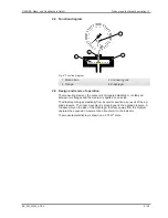
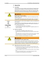
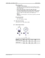
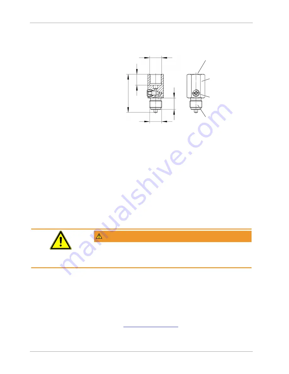
b) Settable damping reactor
In operating mode, the damping throttle must be set so that the output signal
follows the pressure changes with a delay.
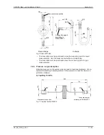
G½
G½
20
66
19
AF27
Setting screw
Connection spigot
according to DIN EN 837-1
Manometer connection
Fig. 8:
Damping reactor MZ410#
3.3 Electrical connections
3.3.1 General information
Only units with installed contacts or a rotation angle transducer are connected
to the power supply.
• By authorized and qualified specialized personnel only.
• When connecting the unit, the national and international electro-technical
regulations must be observed.
• The electrical connection is usually realised via a cable socket mounted to
the side.
• Disconnect the system from the mains, before electrically connecting the
device.
• Please see the type plate for the connection assignment.
WARNING
Operation in areas at risk of explosion
If operated in explosive areas, the electrical data of the unit and the valid local
regulations and guidelines for the installation and operation of electrical systems
in explosive areas must be observed (e.g. DIN EN 60079-14)
Ground connection
The outer ground connection must always be connected to the protective poten-
tial equalisation or a similar local potential equalisation. The connection is suit-
able for connecting fine-wire conductors up to 4 mm
2
or single-wire conductors
up to 6 mm
2
.
3.3.2 Limit switch in accordance with data sheet KE
For more technical information about the contact types and connection options,
please see the data sheet KE. You can request the data sheet on request or via
our webserver
www.fischermesstechnik.de
.


