background image

FISCHER Mess- und Regeltechnik GmbH

Attachments | 8

BA_EN_MA15_ATEX

31 / 36

Fig. 18: 

CE_DE_MA15F_1B_Page2

Summary of Contents for MA15F ... A Series

Page 1: ...al MA15F A B C D Diaphragm manometer for explosive areas Gas explosion protection zone 1 and 2 gases and vapours Dust explosion protection zone 21 and 22 dry dusts 09015053 BA_EN_MA15_ATEX Rev ST4 D 0...

Page 2: ...hotocopy microfilm or another process without the written consent of the company FISCHER Mess und Regeltechnik GmbH Bad Salzuflen Reproduction for internal use is expressly allowed Brand names and pro...

Page 3: ...2 Product and functional description 7 2 1 Delivery scope 7 2 2 Product summary 7 2 3 Intended use 8 2 4 Function diagram 9 2 5 Design and mode of operation 9 3 Assembly 10 3 1 Generalities 10 3 2 Pro...

Page 4: ...by virtue of their specialized training their skills and experience and their knowledge of the pertinent standards WARNING For explosion proof models the specialized personnel must have received spe...

Page 5: ...applies to replacement parts Only the manufacturer is authorised to make any modifications or changes 1 6 Inadmissible Modes of Operation The operational safety of this instrument can only be guarant...

Page 6: ...ource of danger This indicates a potentially dangerous situation that could lead to death or ser ious injury medium danger level a Avoid danger by observing the valid safety regulations CAUTION Type a...

Page 7: ...Contact element Contact element MA15F 0A MA15F 1B 2C 2D Fig 1 Product summary Manometer casing The following options are available for the manometer casing Bayonet ring housing NG100 or NG160 Safety c...

Page 8: ...e Article no Measuring range P max Prod No MA15F83HV87L0100 0 400 mbar 40 bar 587016 01 002 Serial number Contact function KE21M210AH2 Made in Germany 4 1 2 Zero position Switching output U max 250V A...

Page 9: ...the concentric corrugated diaphragm is clamped between two flanges and the medium is applied on one side The diaphragm bulges elastically from its normal position as a result of the ap plied pressure...

Page 10: ...the unit Can be depressurized or taken out of operation Be disconnected from the power supply within the applicable system for re pairs or inspections 3 2 Process connection By authorized and qualifi...

Page 11: ...liquid measurements Vent the pressure line before commissioning The transmitter must be positioned above the measuring point for gas measurements 3 2 2 Pressure surge absorption Pulsating pressure on...

Page 12: ...side Disconnect the system from the mains before electrically connecting the device Please see the type plate for the connection assignment WARNING Operation in areas at risk of explosion If operated...

Page 13: ...temperature 20 C to 60 C Allowed medium temperature in the differential measurement unit 85 C WARNING Compression heat With gaseous mediums the instrument temperature can increase due to com pression...

Page 14: ...asuring range and a pulse frequency 0 06 Hz the temperature in crease is 10K To avoid additional heating the instruments may not be exposed to direct sun light during operation The standards EN60079 0...

Page 15: ...10K To avoid additional heating the instruments may not be exposed to direct sun light during operation The standards EN60079 0 EN 60079 31 EN ISO 80079 36 and EN ISO 80079 37 apply for the non electr...

Page 16: ...he instruments may not be exposed to direct sun light during operation The standards EN60079 0 EN ISO 80079 36 and EN ISO 80079 37 apply for the non electrical part of the devices in terms of explosio...

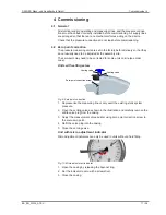
Page 17: ...to be corrected for some units on site see order code Units with setting screw Venting valve Venting valve Zero point correction screw Fig 9 Zero point correction 1 Depressurize the measuring line or...

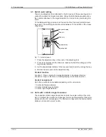
Page 18: ...wards until the drive arm reaches behind the setting pin of the target value indicator 3 Set the target value indicator to the required switch point by turning the key 4 Relieve the axle remove the ad...

Page 19: ...rt The measuring device must be protected against impacts It should be transpor ted in the original packaging or a suitable transport container 5 3 Service All defective or faulty devices should be se...

Page 20: ...TEX 5 5 Disposal WARNING Incorrect disposal may pose a risk to the environment Please help to protect the environment by always disposing of the work pieces and packaging materials in compliance with...

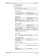
Page 21: ...ad 0 9 x Scale upper value Max pressure flange screw connec tion 160 mm 10 bar 100 mm 40 bar Process connection Connecting shanks G B G B G B 18 NPT 14 NPT M20 x 1 5 Connection flange DIN EN DN20 DN25...

Page 22: ...s usually realised via a cable connection socket mounted to the side of the casing Please refer to the data sheets KE and KE09 for technical data You can re ceive the data sheet on request or download...

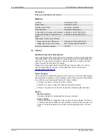
Page 23: ...ed with a protective sheath of PFA or PTFE A FEP covered O Ring made of FKM is used for the flange seal A suitable seal needs to be used on the system side to seal the cladded units Material Optionall...

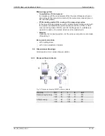
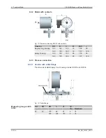
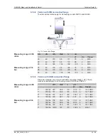
Page 24: ...housing 100 100 130 19 100 90 160 100 160 19 157 120 Safety housing 100 109 130 26 100 90 160 109 160 26 157 120 6 3 3 Process connection 6 3 3 1 Version with collar flange The dimensions stated appl...

Page 25: ...4 M12 25 40 115 68 103 85 4 M12 50 40 165 102 108 125 4 M16 6 3 3 3 Version with ANSI connection flange Dimension drawing see Version with DIN connection flange 25 The di mensions stated apply for al...

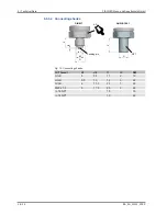
Page 26: ...BA_EN_MA15_ATEX 6 3 3 4 Connecting shanks DIN 837 ANSI B1 20 1 G d1 d2 l1 l2 Centring pin l1 G NPT AF Fig 16 Connecting shanks G Thread d1 d2 l1 l2 SW G B 5 9 5 13 2 19 G B 5 5 13 16 3 22 G B 6 17 5 2...

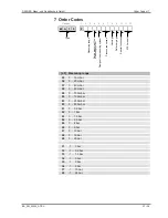
Page 27: ...e Measuring range F 1 2 5 6 7 8 9 10 11 12 3 4 Code no Fluid charging ATEX model 2 3 Measuring range 55 0 16 mbar 56 0 25 mbar 57 0 40 mbar 58 0 60 mbar 59 0 100 mbar 60 0 160 mbar 82 0 250 mbar 83 0...

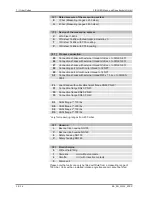
Page 28: ...d 18 NPT 89 Connecting port G with outer thread 14 NPT S2 Connection shanks with external thread M20 x 1 5 acc to DIN EN 3852 FL open flange with collar attachment flange DN50 PN40 F1 Connection flang...

Page 29: ...ment indicator Adjustable marker needle 6 Zero point correction micro adjust ment indicator Resettable drag needle only for measuring ranges from 60 mbar 11 12 ATEX 0A Non electrical unit without swit...

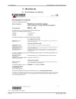
Page 30: ...8 Attachments FISCHER Mess und Regeltechnik GmbH 30 36 BA_EN_MA15_ATEX 8 Attachments 8 1 EU Declarations of conformity Fig 17 CE_DE_MA15F_1B_Page1...

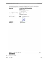
Page 31: ...FISCHER Mess und Regeltechnik GmbH Attachments 8 BA_EN_MA15_ATEX 31 36 Fig 18 CE_DE_MA15F_1B_Page2...

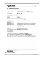
Page 32: ...8 Attachments FISCHER Mess und Regeltechnik GmbH 32 36 BA_EN_MA15_ATEX Fig 19 CE_DE_MA15F_1C_Page1...

Page 33: ...FISCHER Mess und Regeltechnik GmbH Attachments 8 BA_EN_MA15_ATEX 33 36 Fig 20 CE_DE_MA15F_1C_Page2...

Page 34: ...8 Attachments FISCHER Mess und Regeltechnik GmbH 34 36 BA_EN_MA15_ATEX Fig 21 CE_DE_MA15F_2D_Page1...

Page 35: ...FISCHER Mess und Regeltechnik GmbH Attachments 8 BA_EN_MA15_ATEX 35 36 Fig 22 CE_DE_MA15F_2D_Page2...

Page 36: ...8 Attachments FISCHER Mess und Regeltechnik GmbH 36 36 BA_EN_MA15_ATEX Fig 23 CE_DE_MA15F_0A...

Reviews: