ROBO TX ElectroPneumatic
COMPUTING
11
Connect the color sensor to I3 using with the black and green cable and to + with the
red cable (see circuit diagram in assembly instructions).
Task 1 - Defining color values:
First check the values output by the ROBO TX Controller for the parts in the inter-
face test (white, red, blue). Use the interface test in ROBO Pro for this purpose.
Set input I3, connected to the color sensor, to analog 10V (color sensor).
Make a small table and enter the values you have measured. Also observe the changes
when the distance to the colored surface or the ambient light changes.
In addition a light barrier is used for the next task. This consists of a light-sensitive sen-
sor (phototransistor) and a lens tip lamp (actuator) as light source.
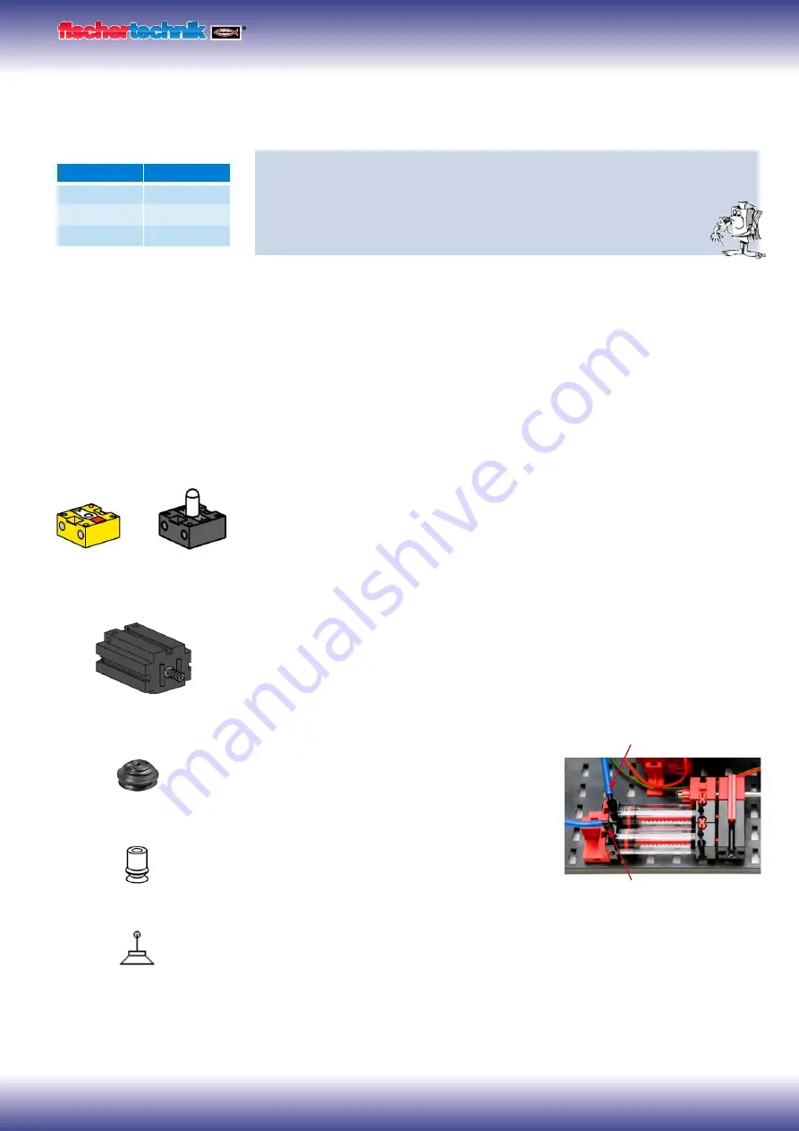
Sensors and actuators
Phototransistor
You can also call the phototransistor a "brightness sensor." This is a "sensor" that reacts
to brightness. In a light barrier it is the counter-part of the lens tip lamp. When there
is a high degree of brightness, that is when the transistor receives light from the lens
tip lamp, it conducts electricity. If the light beam is interrupted, the transistor does not
conduct any electricity. Caution! Pay attention to the polarity when connecting the
phototransistor to the power supply. Red = positive.
Lens tip lamp
This is an incandescent bulb with built-in lens to focus the light. It is required to build a
light barrier. The lens tip lamp can be recognized by its gray base.
Electric motor
The direct current motor converts electrical energy into mechanical energy. This results
in the rotational movement of the motor. A motor also has a gearbox. With this gearbox
you can reduce the speed of the motor and simultaneously increase the
torque
(motor
pulling force).
Vacuum pump
You need a vacuum pump for the model to pro-
duce the vacuum to pick up the parts. Since the
vacuum pumps used for industrial applications are
very expensive, you can use a simpler solution for
producing a vacuum. You need two cylinders with
connected piston rods. Connect connection A to
the compressor over the solenoid valve. Connec-
tion B leads to the suction cup. When the valve
is actuated, both pistons are pushed forward. If
the suction cup is positioned on a part, the air is
sucked in by the two pistons producing a vacuum.
The bellows type suction cup has a lifting function and can be used on flat as well as
slightly arched surfaces.
Color
Value
White
Red
Blue
Light barrier
Phototransistor
(sensor)
Lamp
(actuator)
+
B
A
fischertechnik suction cup
Bellows suction cup
Suction cup circuit diagram
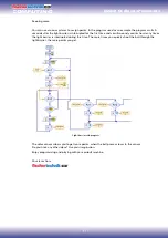
Summary of Contents for COMPUTING ROBO TX ElectroPneumatic
Page 1: ......


