321144
103
Step 4:
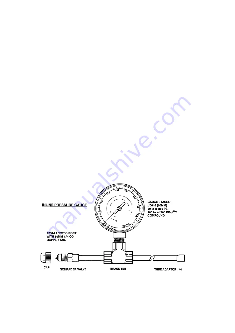
Connect a nitrogen bottle to the in-line pressure gauge by means of a hose with a Schrader valve
depressing key in the hose coupling.
Step 5:
Open the nitrogen bottle fully with the regulator backed off.
Step 6:
Increase the regulator pressure in the circuit being tested to
150 psi.
Step 7:
Close the nitrogen bottle valve, then back off the pressure regulator.
Step 8:
Disconnect the hose coupling to the Schrader valve fitting.
Step 9:
Seal the Schrader valve with its sealing cap.
Step 10:
Use a bit of masking tape to mark the face of the pressure gauge at the set pressure. Record date and time
on the tape also.
Step 11:
Check all exposed brazed joints with soap bubbles, including the joints on the in-line pressure gauge.
Step 12:
Allow the pipe circuit under test to sit on drop off test. This could take a number of days for a result.
NOTE:
In some cases a leak may not be found by pressurising the circuit, whereas a vacuum pulled on the
same circuit will. Keep this in mind as oil within the circuit can block a hole.
In some cases, if the brazed joint is warmed while under pressure, this can thin the oil and help to expose
the leak. A heat gun or hair dryer is useful.
Diagram 0
Summary of Contents for 635 Active Smart
Page 1: ...321144 Service Manual 635 680 790 900 Active Smart Refrigerator Freezer R134a R600a Systems...
Page 2: ...321144 2...
Page 96: ...321144 96 Photo 12 22 5...
Page 100: ...321144 100 Diagram 12 25...
Page 108: ...321144 108 13 11 Embraco Compressor Fitted With External Overload Diagram 13 11...
Page 114: ...321144 114 14 2 Non Ice Water Models Wiring Diagram...
Page 116: ...321144 116 14 4 Ice Water Models Wiring Diagram...
Page 117: ...321144 117 14 5 900 Models Power Control Module Wiring Connections Reciprocating Compressor...
Page 118: ...321144 118 14 6 900 Models Wiring Diagram Reciprocating Compressor...
Page 119: ...321144 119 14 7 900 Models Power Control Module Wiring Connections VC Compressor...
Page 120: ...321144 120 14 8 900 Models Wiring Diagram VC Compressor...
Page 121: ...321144 121 14 9 B Model Wiring Route Diagram 14 9...
Page 122: ...321144 122 14 10 T Model Wiring Route Diagram 14 10...
Page 145: ......


