321144
129
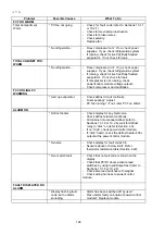
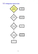
Problem
Possible Causes
What To Do
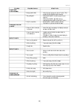
LIGHT NOT
FUNCTIONING
* Blown LED PCB.
- Check power supply to socket 7 volts. If nil,
check plug at power/control module.
* Reed Switch.
- Check reed switch is working by using a
magnet.
- Check reed switch operation using
Input/Output test (refer to Section 10.2.4).
* Poor connection.
- Lamp holder, replace where possible.
- Connector on power/control module.
CONSOLE NO LED
LIGHTS
* Power/control module
no power.
- Check harness and plugs on display module
harness at both ends.
* Power/control module
not initialised.
- Initialise power/control module (refer to
Section 12.4.1).
- If raspberry noise made when attempting to
initialize, check door switches.
NOISY FAN PC
* Ice around gasket.
- Replace assembly with new fan kit.
* Wires touching.
- Tuck wires away from fan blade.
* Faulty fan.
- Replace fan.
NOISY FAN FC
* Ice on cover.
- Clear ice off cover and check doors are
sealing.
* Ice on grill.
- Clear ice off grill and check doors are sealing.
* Fan off mountings.
- Refit.
* Wires touching.
- Tuck wires away from fan blade.
* Capillary touching.
- Shift capillary from fan area make sure it is not
touching any part of the cabinet.
* Fan motor noisy.
- Fit replacement.
* Wires too tight.
- Re route wiring.
ICE BUILD UP
COMPARTMENT
* Doors not sealing.
- Check gaskets sealing, adjust gaskets.
- Fit drain valve to drain tube.
Summary of Contents for 635 Active Smart
Page 1: ...321144 Service Manual 635 680 790 900 Active Smart Refrigerator Freezer R134a R600a Systems...
Page 2: ...321144 2...
Page 96: ...321144 96 Photo 12 22 5...
Page 100: ...321144 100 Diagram 12 25...
Page 108: ...321144 108 13 11 Embraco Compressor Fitted With External Overload Diagram 13 11...
Page 114: ...321144 114 14 2 Non Ice Water Models Wiring Diagram...
Page 116: ...321144 116 14 4 Ice Water Models Wiring Diagram...
Page 117: ...321144 117 14 5 900 Models Power Control Module Wiring Connections Reciprocating Compressor...
Page 118: ...321144 118 14 6 900 Models Wiring Diagram Reciprocating Compressor...
Page 119: ...321144 119 14 7 900 Models Power Control Module Wiring Connections VC Compressor...
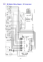
Page 120: ...321144 120 14 8 900 Models Wiring Diagram VC Compressor...
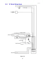
Page 121: ...321144 121 14 9 B Model Wiring Route Diagram 14 9...
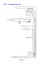
Page 122: ...321144 122 14 10 T Model Wiring Route Diagram 14 10...
Page 145: ......


