321144
25
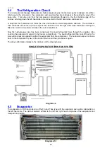
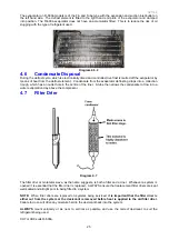
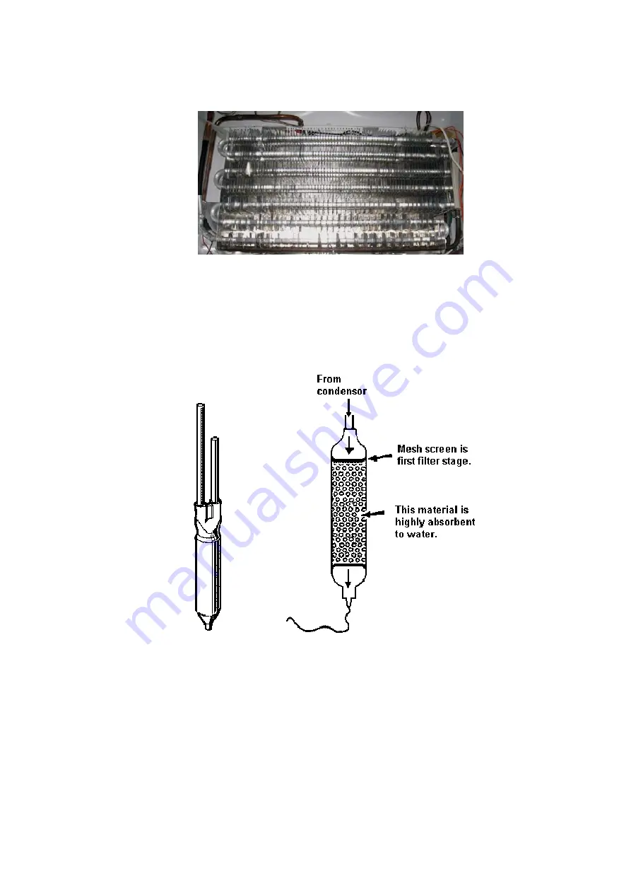
The evaporator on R-600a models is of the Fin and Tube type with the expansion and suction inlet/outlet on
the left hand side. The defrost element is fitted to the right hand end plate of the evaporator and clamped
into position. The R-600a evaporator does not have an accumulator fitted. This is to reduce the risk of oil
slugging with the type of refrigerant used.
Diagram 4.5.2
4.6
Condensate Disposal
During the defrost cycle, which is electronically timed and controlled, live frost is melted off the evaporator by
means of heat from the defrost element. Condensate from the evaporator defrosting drops into a collection
trough, which has an outlet hole in the centre of the liner. A tube then allows the condensate to flow into a
water evaporation tray above the compressor.
4.7
Filter Drier
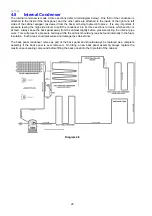
Diagram 4.7
The filter drier or molecular sieve, as the name suggests, is both a filter and a drier. Whenever a system is
opened it is essential that the filter drier is replaced. ALWAYS ensure that replacement filter driers are kept
well sealed and airtight prior to being fitted to a system.
NOTE:
When filter driers are replaced on systems being serviced,
it is important that the filter drier is
either cut from the system or the desiccant is removed before heat is applied to the old filter drier.
Failure to do so will drive any moisture held in the desiccant back into the system.
ALWAYS
mount vertically or as near to vertical as possible and use the correct desiccant to suit the
refrigerant being used.
XH7 or XH9 suits R-600a.
Summary of Contents for 635 Active Smart
Page 1: ...321144 Service Manual 635 680 790 900 Active Smart Refrigerator Freezer R134a R600a Systems...
Page 2: ...321144 2...
Page 96: ...321144 96 Photo 12 22 5...
Page 100: ...321144 100 Diagram 12 25...
Page 108: ...321144 108 13 11 Embraco Compressor Fitted With External Overload Diagram 13 11...
Page 114: ...321144 114 14 2 Non Ice Water Models Wiring Diagram...
Page 116: ...321144 116 14 4 Ice Water Models Wiring Diagram...
Page 117: ...321144 117 14 5 900 Models Power Control Module Wiring Connections Reciprocating Compressor...
Page 118: ...321144 118 14 6 900 Models Wiring Diagram Reciprocating Compressor...
Page 119: ...321144 119 14 7 900 Models Power Control Module Wiring Connections VC Compressor...
Page 120: ...321144 120 14 8 900 Models Wiring Diagram VC Compressor...
Page 121: ...321144 121 14 9 B Model Wiring Route Diagram 14 9...
Page 122: ...321144 122 14 10 T Model Wiring Route Diagram 14 10...
Page 145: ......


