321144
29
4.9
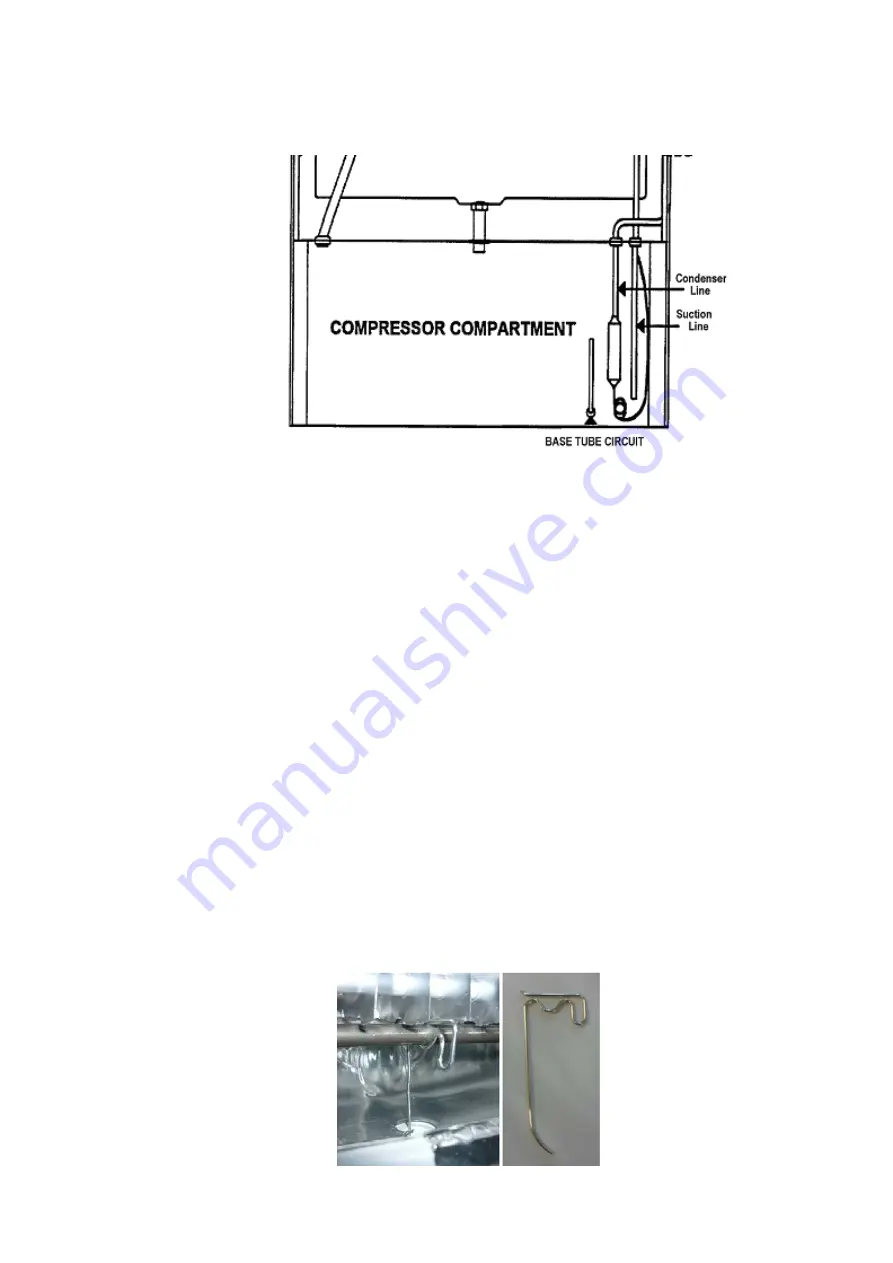
Compressor Compartment Layout
The diagrams below will assist in identifying the various pipes within the compressor compartment. They
should be read in conjunction with the full system diagram (refer to Diagram 4.4).
Diagram 4.9
4.10 Cross Rail
The cross rail contains part of the condenser copper tubing (mullion heater) providing heat to the gasket
area between the PC and FC compartments, preventing sweating of the gasket. Also mounted on the cross
rail is the Reed Sensor, under the plastic cover in the centre.
4.11 Door and Door Hinge
On the Designer models, the upper door hinge is concealed and cannot be seen with the door closed. The
upper door height is extended past the top of the cabinet to cover the hinge area.
4.12 Compressor
The compressor is turned on when cooling is required. It is switched by a Triac (solid state switching device)
on the power/control module.
4.13 Thermal Fuse
There are two thermal fuses mounted in the wiring harness of the defrost element, having a tripping
temperature of 72
O
C. Once open circuit they cannot be reset. Replacement is part of the element heater
assembly.
These fuses in both leads of the element protect the refrigerator from any over heating through failure of the
element itself or a triac failure in the power/control module. Both sides are protected in case phase and
neutral are reversed.
NOTE:
Care should be taken if manually defrosting the evaporator if using heat guns, that the thermal fuses
are not over heated.
4.14 Drain Heater Wire
A drain heater wire is fitted to all cabinets except R134a B models. This drain heater helps to prevent the
drain tube from blocking with ice. The wire clips onto the double-pass defrost element, with the tail of the
heater wire in the drain tube, thus conducting heat from the defrost element into the drain tube area during
defrost.
Diagram 4.14
Summary of Contents for 635 Active Smart
Page 1: ...321144 Service Manual 635 680 790 900 Active Smart Refrigerator Freezer R134a R600a Systems...
Page 2: ...321144 2...
Page 96: ...321144 96 Photo 12 22 5...
Page 100: ...321144 100 Diagram 12 25...
Page 108: ...321144 108 13 11 Embraco Compressor Fitted With External Overload Diagram 13 11...
Page 114: ...321144 114 14 2 Non Ice Water Models Wiring Diagram...
Page 116: ...321144 116 14 4 Ice Water Models Wiring Diagram...
Page 117: ...321144 117 14 5 900 Models Power Control Module Wiring Connections Reciprocating Compressor...
Page 118: ...321144 118 14 6 900 Models Wiring Diagram Reciprocating Compressor...
Page 119: ...321144 119 14 7 900 Models Power Control Module Wiring Connections VC Compressor...
Page 120: ...321144 120 14 8 900 Models Wiring Diagram VC Compressor...
Page 121: ...321144 121 14 9 B Model Wiring Route Diagram 14 9...
Page 122: ...321144 122 14 10 T Model Wiring Route Diagram 14 10...
Page 145: ......

