321144
33
Diagram 4.20.1
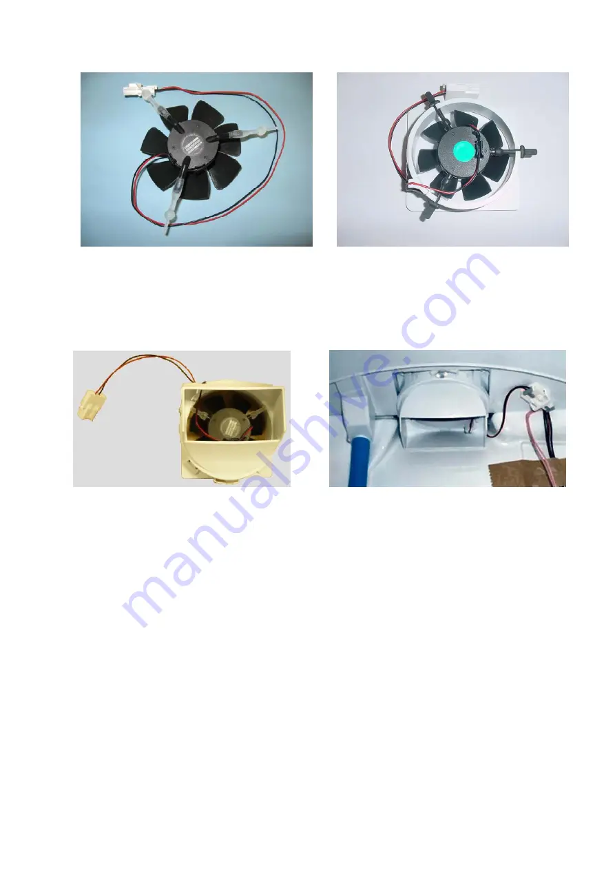
4.20.2 “T” Model PC Fan
The PC fan in the “T” model cabinets has an air shroud duct fitted to the base of the fan. This is to deflect
the airflow down the duct and prevent air leaks in the area of the top of the duct.
“T” Model PC Fan
Fan in Position
Diagram 4.20.2
NOTE:
The same PC fan assembly is supplied as a spare part for both “B” and “T” models. This part
comes with the air shroud duct for use in “T” models. When the spare part is used in “B” models, the air
shroud duct should be discarded, as it is not used in “B” models.
“B” Model PC Fan (Viewed from PC side)
FC Fan (Viewed from front)
Summary of Contents for 635 Active Smart
Page 1: ...321144 Service Manual 635 680 790 900 Active Smart Refrigerator Freezer R134a R600a Systems...
Page 2: ...321144 2...
Page 96: ...321144 96 Photo 12 22 5...
Page 100: ...321144 100 Diagram 12 25...
Page 108: ...321144 108 13 11 Embraco Compressor Fitted With External Overload Diagram 13 11...
Page 114: ...321144 114 14 2 Non Ice Water Models Wiring Diagram...
Page 116: ...321144 116 14 4 Ice Water Models Wiring Diagram...
Page 117: ...321144 117 14 5 900 Models Power Control Module Wiring Connections Reciprocating Compressor...
Page 118: ...321144 118 14 6 900 Models Wiring Diagram Reciprocating Compressor...
Page 119: ...321144 119 14 7 900 Models Power Control Module Wiring Connections VC Compressor...
Page 120: ...321144 120 14 8 900 Models Wiring Diagram VC Compressor...
Page 121: ...321144 121 14 9 B Model Wiring Route Diagram 14 9...
Page 122: ...321144 122 14 10 T Model Wiring Route Diagram 14 10...
Page 145: ......


