321144
37
5
ELECTRONICS SECTION
5.1
Diagrammatic Overview Function Description
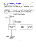
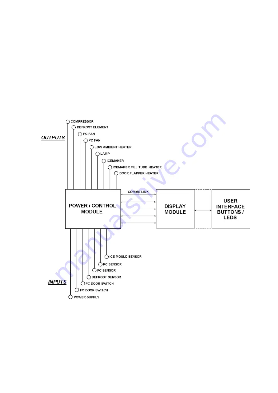
The electronic system consists of several parts:
Power/control module, display module, compressor, defrost heater, low ambient heater, door flapper heater,
produce compartment fan, freezer compartment fan, light, temperature sensors, icemaker sensors,
solenoids and door sensors.
The purpose of the power/control module is to turn on the compressor, which cools the evaporator, then to
use the fans to efficiently cool the compartments. Both fans turn on with the compressor. The freezer
compartment (FC) fan is kept at a constant speed while the produce compartment (PC) fan is regulated to
provide the balanced cooling for both compartments. The function of the microprocessor in the
power/control module is to provide independence of both compartments to their set temperatures, although
the environment of one compartment effects the other as they are linked by the ducts as can seen by the
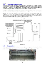
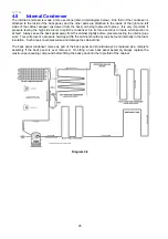
internal air flow of the cabinet. (Refer to diagrams 4.2, 4.2.2A and 4.2.2B).
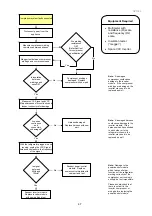
ELECTRONIC FUNCTIONAL SCHEMATIC
Diagram 5.1
Summary of Contents for 635 Active Smart
Page 1: ...321144 Service Manual 635 680 790 900 Active Smart Refrigerator Freezer R134a R600a Systems...
Page 2: ...321144 2...
Page 96: ...321144 96 Photo 12 22 5...
Page 100: ...321144 100 Diagram 12 25...
Page 108: ...321144 108 13 11 Embraco Compressor Fitted With External Overload Diagram 13 11...
Page 114: ...321144 114 14 2 Non Ice Water Models Wiring Diagram...
Page 116: ...321144 116 14 4 Ice Water Models Wiring Diagram...
Page 117: ...321144 117 14 5 900 Models Power Control Module Wiring Connections Reciprocating Compressor...
Page 118: ...321144 118 14 6 900 Models Wiring Diagram Reciprocating Compressor...
Page 119: ...321144 119 14 7 900 Models Power Control Module Wiring Connections VC Compressor...
Page 120: ...321144 120 14 8 900 Models Wiring Diagram VC Compressor...
Page 121: ...321144 121 14 9 B Model Wiring Route Diagram 14 9...
Page 122: ...321144 122 14 10 T Model Wiring Route Diagram 14 10...
Page 145: ......


