321144
39
There are two types of power/control modules used on these Active Smart
®
cabinets, one for non-ice &
water cabinets and the other for those cabinets having the ice & water feature.
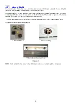
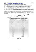
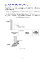
Non-Ice & Water Module
Ice & Water Module
Diagram 5.3
5.4
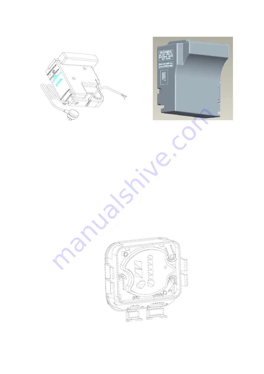
Display Module
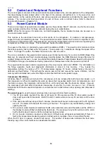
On the non-ice & water models, this module contains the user interface. It is controlled via a 5-wire
communications interface from the power/control module.
The user interface of push button switches and Light Emitting Diode (LED) display on the display module
printed circuit board is used to input and display the required set temperatures for the refrigerator
compartments.
The user interface is positioned at the right hand side of the fresh food compartment (PC). The interface
automatically displays the current temperature setting for the PC compartment. This is shown as a series of
LED lights on a thermometer symbol. To adjust the temperature of the PC, simply press the
TEMPERATURE
UP
or
TEMPERATURE DOWN
buttons to the appropriate setting (refer to Section 4.23.2).
Press the
MODE
button on the left-hand side of the interface to select the FC compartment setting. The
indicator light will flash for 8 seconds to show a new compartment has been selected. Press the up or down
buttons to adjust the temperature as necessary.
Further presses of the
MODE
button will toggle between the PC and FC compartments.
Non-Ice & Water Display Module
Diagram 5.4
Summary of Contents for 635 Active Smart
Page 1: ...321144 Service Manual 635 680 790 900 Active Smart Refrigerator Freezer R134a R600a Systems...
Page 2: ...321144 2...
Page 96: ...321144 96 Photo 12 22 5...
Page 100: ...321144 100 Diagram 12 25...
Page 108: ...321144 108 13 11 Embraco Compressor Fitted With External Overload Diagram 13 11...
Page 114: ...321144 114 14 2 Non Ice Water Models Wiring Diagram...
Page 116: ...321144 116 14 4 Ice Water Models Wiring Diagram...
Page 117: ...321144 117 14 5 900 Models Power Control Module Wiring Connections Reciprocating Compressor...
Page 118: ...321144 118 14 6 900 Models Wiring Diagram Reciprocating Compressor...
Page 119: ...321144 119 14 7 900 Models Power Control Module Wiring Connections VC Compressor...
Page 120: ...321144 120 14 8 900 Models Wiring Diagram VC Compressor...
Page 121: ...321144 121 14 9 B Model Wiring Route Diagram 14 9...
Page 122: ...321144 122 14 10 T Model Wiring Route Diagram 14 10...
Page 145: ......

