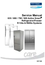
321144
4
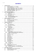
CONTENTS
1
SPECIFICATIONS ...................................................................................................................................8
1.1
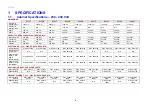
Cabinet Specifications – 230 - 240 Volt....................................................................................8
1.2
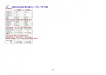
Cabinet Specifications – 110 - 115 Volt..................................................................................10
1.3
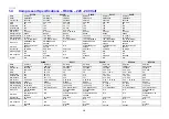
Compressor Specifications – R134a – 220 - 240 Volt............................................................11
1.4
Compressor Specifications – R600a – 220 - 240 Volt............................................................12
1.5
Compressor Specifications – R134a – 110 - 115 Volt............................................................13
1.6
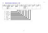
Model Number Identification – 635 / 680 / 790 .......................................................................14
1.7
Model Number Identification – 900 .........................................................................................15
2
SERVICING REQUIREMENTS..............................................................................................................16
2.1
Specialised Service Tools.......................................................................................................16
2.1.1
Static Strap .........................................................................................................................16
2.1.2
Interface Light Pen Mk 2 ....................................................................................................16
2.2
Health & Safety .......................................................................................................................16
2.2.1
Good Work Practices .........................................................................................................16
2.2.2
Environmental Health And Safety ......................................................................................16
2.2.3
Good Practice And Safety..................................................................................................16
3
INSTALLATION INSTRUCTIONS .........................................................................................................17
3.1
Levelling ..................................................................................................................................17
3.2
Door Hinging (Tasman Models Only) .....................................................................................18
3.3
Air Space Requirements .........................................................................................................18
3.4
Temperature Adjustment ........................................................................................................18
4
THEORY OF OPERATION ....................................................................................................................19
4.1
Terms ......................................................................................................................................19
4.2
Internal Air Flow ......................................................................................................................20
4.2.1
Ice & Water Models ............................................................................................................20
4.2.2
Non Ice & Water Models ....................................................................................................21
4.3
Defrost Cycle...........................................................................................................................22
4.3.1
R134a System....................................................................................................................22
4.3.2
R600a System....................................................................................................................23
4.4
The Refrigeration Circuit .........................................................................................................24
4.5
Evaporator...............................................................................................................................24
4.6
Condensate Disposal..............................................................................................................25
4.7
Filter Drier ...............................................................................................................................25
4.8
Internal Condenser .................................................................................................................26
4.8.1
Condenser Lay Out 635 / 680 / 790 "T" Models ................................................................27
4.8.2
Condenser Lay Out 635 / 680 / 790 / 900 "B" Models .......................................................28
4.9
Compressor Compartment Layout..........................................................................................29
4.10
Cross Rail................................................................................................................................29
4.11
Door and Door Hinge ..............................................................................................................29
4.12
Compressor.............................................................................................................................29
4.13
Thermal Fuse ..........................................................................................................................29
4.14
Drain Heater Wire ...................................................................................................................29
4.15
Divider Partition.......................................................................................................................30
4.16
LCD Display Panel ..................................................................................................................31
4.17
Door Switches .........................................................................................................................31
4.18
Defrost Heater.........................................................................................................................31
4.19
Low Ambient Heater................................................................................................................32
4.20
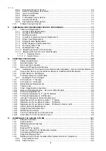
PC / FC Fans ..........................................................................................................................32
4.20.1
“B” Model Fan.....................................................................................................................32
4.20.2
“T” Model PC Fan...............................................................................................................33
4.21
Interior Light ............................................................................................................................34
4.22
Thermistor Temperature Sensors...........................................................................................35
4.23
Basic Operation.......................................................................................................................36
4.23.1
Temperature Adjustment – Ice & Water Models ................................................................36
4.23.2
Temperature Adjustment – Non-Ice & Water Models ........................................................36
5
ELECTRONICS SECTION.....................................................................................................................37
5.1
Diagrammatic Overview Function Description........................................................................37
5.2
Control and Peripheral Functions ...........................................................................................38
5.3
Power/Control Module ............................................................................................................38
Summary of Contents for 635 Active Smart
Page 1: ...321144 Service Manual 635 680 790 900 Active Smart Refrigerator Freezer R134a R600a Systems...
Page 2: ...321144 2...
Page 96: ...321144 96 Photo 12 22 5...
Page 100: ...321144 100 Diagram 12 25...
Page 108: ...321144 108 13 11 Embraco Compressor Fitted With External Overload Diagram 13 11...
Page 114: ...321144 114 14 2 Non Ice Water Models Wiring Diagram...
Page 116: ...321144 116 14 4 Ice Water Models Wiring Diagram...
Page 117: ...321144 117 14 5 900 Models Power Control Module Wiring Connections Reciprocating Compressor...
Page 118: ...321144 118 14 6 900 Models Wiring Diagram Reciprocating Compressor...
Page 119: ...321144 119 14 7 900 Models Power Control Module Wiring Connections VC Compressor...
Page 120: ...321144 120 14 8 900 Models Wiring Diagram VC Compressor...
Page 121: ...321144 121 14 9 B Model Wiring Route Diagram 14 9...
Page 122: ...321144 122 14 10 T Model Wiring Route Diagram 14 10...
Page 145: ......

