321144
45
Step 1 – Check the compressor windings resistance.
•
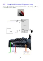
With the refrigerator disconnected from the power supply, remove the compressor cover and unplug the fusite
terminal connection from the compressor.
•
Select the Ohms range on the multi-meter and measure the resistance of all three windings. The
resistance should be the same across all three windings. Refer to winding resistances in compressor
specifications, Sections 1.3, 1.4 and 1.5.
•
Check for leakage to ground from the windings within the compressor.
•
Reconnect the fusite plug to the compressor and refit the compressor cover.
Step 2 – Check the input voltage to the inverter.
•
Remove the protective terminal cover from the inverter, reconnect the appliance to the power supply and
set the compressor running.
•
Select the multi-meter to measure AC volts. With the probes measure the input voltage as shown at the
two terminals indicated or at the input harness edge connector.
A normal cabinet with no fault:
•
Will measure mains voltage (110volts or 230volts) AC input into the inverter.
•
The compressor will be running (this can be felt by placing a hand on the compressor shell).
•
The LED on the inverter board will be flashing once every 15 seconds as all is normal.
AC input neutral/phase
At the back of the edge
connector
Ω
Ω
Ω
OR
Summary of Contents for 635 Active Smart
Page 1: ...321144 Service Manual 635 680 790 900 Active Smart Refrigerator Freezer R134a R600a Systems...
Page 2: ...321144 2...
Page 96: ...321144 96 Photo 12 22 5...
Page 100: ...321144 100 Diagram 12 25...
Page 108: ...321144 108 13 11 Embraco Compressor Fitted With External Overload Diagram 13 11...
Page 114: ...321144 114 14 2 Non Ice Water Models Wiring Diagram...
Page 116: ...321144 116 14 4 Ice Water Models Wiring Diagram...
Page 117: ...321144 117 14 5 900 Models Power Control Module Wiring Connections Reciprocating Compressor...
Page 118: ...321144 118 14 6 900 Models Wiring Diagram Reciprocating Compressor...
Page 119: ...321144 119 14 7 900 Models Power Control Module Wiring Connections VC Compressor...
Page 120: ...321144 120 14 8 900 Models Wiring Diagram VC Compressor...
Page 121: ...321144 121 14 9 B Model Wiring Route Diagram 14 9...
Page 122: ...321144 122 14 10 T Model Wiring Route Diagram 14 10...
Page 145: ......


