321144
50
7.3.5
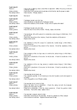
Sabbath Mode
When in this mode, the alarms are deactivated and the interior light
and back light on the display will not come on. The interior fan will
not turn off when the door is opened.
7.3.6
Key Silent Mode
When in this mode, the beeper does not operate when the buttons
on the keypad are pressed.
NOTE:
Faults, bottle chill, and the door
will still alarm when the refrigerator is set in Key Silent mode.
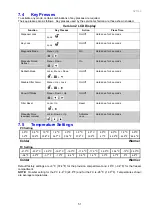
When this icon is displayed, it indicates the product is in Key Silent
mode.
To activate or deactivate, hold the
MENU
button for four (4)
seconds.
7.3.7
Dispenser Lock
This mode disables the water dispensing pad and prevents water
from being dispensed.
To activate this mode, press the
LOCK
button for 2 seconds.
7.3.8
Key Lock
This mode disables all the buttons.
To activate this mode, press the
LOCK
button for 4 seconds.
7.3.9
Filter Replacement Alert
This
icon will appear when the water filter needs changing. The
filter needs replacing every 2800 Litres or 6 months. This will flash
when dispensing water.
To deactivate the warning, press the
LOCK
and
UP
buttons
simultaneously for 4 seconds.
Summary of Contents for 635 Active Smart
Page 1: ...321144 Service Manual 635 680 790 900 Active Smart Refrigerator Freezer R134a R600a Systems...
Page 2: ...321144 2...
Page 96: ...321144 96 Photo 12 22 5...
Page 100: ...321144 100 Diagram 12 25...
Page 108: ...321144 108 13 11 Embraco Compressor Fitted With External Overload Diagram 13 11...
Page 114: ...321144 114 14 2 Non Ice Water Models Wiring Diagram...
Page 116: ...321144 116 14 4 Ice Water Models Wiring Diagram...
Page 117: ...321144 117 14 5 900 Models Power Control Module Wiring Connections Reciprocating Compressor...
Page 118: ...321144 118 14 6 900 Models Wiring Diagram Reciprocating Compressor...
Page 119: ...321144 119 14 7 900 Models Power Control Module Wiring Connections VC Compressor...
Page 120: ...321144 120 14 8 900 Models Wiring Diagram VC Compressor...
Page 121: ...321144 121 14 9 B Model Wiring Route Diagram 14 9...
Page 122: ...321144 122 14 10 T Model Wiring Route Diagram 14 10...
Page 145: ......


