321144
62
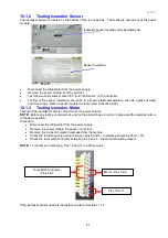
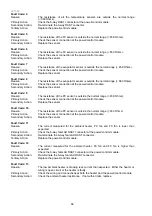
The alternative method of testing the icemaker unit is to use a 9-volt battery plus battery terminal and a multi
meter. The meter probes should be placed into the back of the icemaker 4 way socket onto the yellow and
blue wires. Check the continuity of the circuit to the tact switch in the ice mould tray. The switch should be
closed.
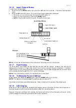
By applying a 9 volt DC supply across the white and red wires of the plug to the icemaker motor, it is
possible to drive the ice mould tray forward to a full twist of the tray and the tact switch will close again.
Note:
•
9-volt battery positive to the red wire to go forward.
•
9-volt battery positive to the white wire to go backwards.
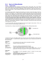
Checking the tact switch
Advancing the motor
10.1.4 Testing Water Valve
The water valves are located in the compressor unit compartment.
•
Disconnect the refrigerator from the power supply.
•
Remove the connector from the valve.
•
Resistance of the water valves is 14
Ω
± 5% (blue coils) and 10
Ω
± 5% (red coils).
When testing for voltage at the ice or water valve:
•
Disconnect the refrigerator from the power supply.
•
Remove the connector from the water valve.
•
Place the meter probes into the connector of the valve that is faulty (ice valve or water dispenser
valve).
•
Reconnect the refrigerator to the power supply.
•
Place a glass into the dispenser to operate the valve (for water dispenser valve only).
•
Place the product into a forced harvest (for icemaker only).
The voltage at the connector (once disconnected from the valve) should be 12 volts DC. Care should be
taken not to damage the connector or wiring.
Summary of Contents for 635 Active Smart
Page 1: ...321144 Service Manual 635 680 790 900 Active Smart Refrigerator Freezer R134a R600a Systems...
Page 2: ...321144 2...
Page 96: ...321144 96 Photo 12 22 5...
Page 100: ...321144 100 Diagram 12 25...
Page 108: ...321144 108 13 11 Embraco Compressor Fitted With External Overload Diagram 13 11...
Page 114: ...321144 114 14 2 Non Ice Water Models Wiring Diagram...
Page 116: ...321144 116 14 4 Ice Water Models Wiring Diagram...
Page 117: ...321144 117 14 5 900 Models Power Control Module Wiring Connections Reciprocating Compressor...
Page 118: ...321144 118 14 6 900 Models Wiring Diagram Reciprocating Compressor...
Page 119: ...321144 119 14 7 900 Models Power Control Module Wiring Connections VC Compressor...
Page 120: ...321144 120 14 8 900 Models Wiring Diagram VC Compressor...
Page 121: ...321144 121 14 9 B Model Wiring Route Diagram 14 9...
Page 122: ...321144 122 14 10 T Model Wiring Route Diagram 14 10...
Page 145: ......


