321144
64
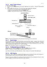
Input/Output Status
Press the
UP
button once more – Input/Output status.
IO
shown indicates the product is in input/output status. The LCDs that are highlighted indicate what
components are on (refer to Section 10.1.6).
NOTE:
When the PC door is opened, the backlight will turn off. The LCD for the FC or PC door will come
on when either door is opened.
The IO shown stands for Input/Output, not a temperature.
Diagram D
Input/Output Status
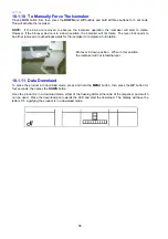
PC2 Sensor Temperature
Press the
UP
button once more – PC2 sensor. This sensor is attached to the water tank.
NOTE:
5.0 shown indicates the temperature of the PC2 sensor is 5
O
C (41
O
F).
Diagram E
PC Sensor 2
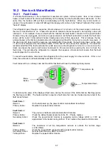
Icemaker Sensor Temperature
Press the
UP
button once more – Icemaker sensor.
NOTE:
12.0 min shown indicates the temperature of the Icemaker sensor is -12
O
C (10.4
O
F).
Diagram F
Icemaker Sensor
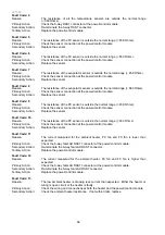
Fault History
Press the
UP
button once more – Fault History.
H O
will be showing.
Diagram G
Fault History
To exit the diagnostic mode, press the
MENU
button. If not terminated manually, the diagnostic mode will
time out and go back to default display after 5 minutes.
Summary of Contents for 635 Active Smart
Page 1: ...321144 Service Manual 635 680 790 900 Active Smart Refrigerator Freezer R134a R600a Systems...
Page 2: ...321144 2...
Page 96: ...321144 96 Photo 12 22 5...
Page 100: ...321144 100 Diagram 12 25...
Page 108: ...321144 108 13 11 Embraco Compressor Fitted With External Overload Diagram 13 11...
Page 114: ...321144 114 14 2 Non Ice Water Models Wiring Diagram...
Page 116: ...321144 116 14 4 Ice Water Models Wiring Diagram...
Page 117: ...321144 117 14 5 900 Models Power Control Module Wiring Connections Reciprocating Compressor...
Page 118: ...321144 118 14 6 900 Models Wiring Diagram Reciprocating Compressor...
Page 119: ...321144 119 14 7 900 Models Power Control Module Wiring Connections VC Compressor...
Page 120: ...321144 120 14 8 900 Models Wiring Diagram VC Compressor...
Page 121: ...321144 121 14 9 B Model Wiring Route Diagram 14 9...
Page 122: ...321144 122 14 10 T Model Wiring Route Diagram 14 10...
Page 145: ......

