321144
88
12 SERVICING PROCEDURES
12.1 Safety Considerations
CAUTION
ALL TERMINALS AND INTERNAL PARTS SHOULD BE
TREATED AS LIVE.
ALL SERVICING SHOULD BE CARRIED OUT WITH THE REFRIGERATOR
DISCONNECTED FROM THE POWER SUPPLY.
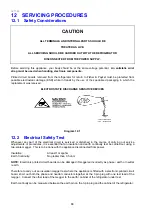
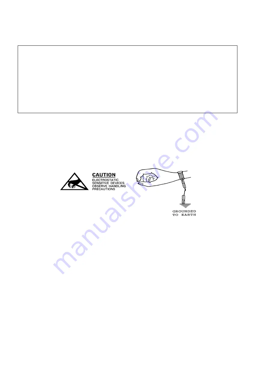
Before servicing this appliance, your body should be at the same voltage potential.
An antistatic wrist
strap must be used when handling electronic components.
Printed circuit boards removed from the refrigerator for return to Fisher & Paykel must be protected from
possible electrostatic damage (ESD) while in transit by the use of the specialised packaging in which the
replacement was received.
ELECTROSTATIC DISCHARGE SENSITIVE DEVICES
Diagram 12.1
12.2 Electrical Safety Test
Whenever any part of the electrical circuit is serviced or disturbed in the course of carrying out service
adjustments or procedures, it is essential that an insulation and earth continuity test be carried out using a
two-scale megger. This is to be done with the appliance disconnected from power.
Insulation:
At least 1 megohm
Earth Continuity:
No greater than 0.5 ohm
NOTE:
Electronic printed circuit boards can be damaged if meggered incorrectly as phase / earth or neutral
/ earth.
Therefore to carry out an insulation megger test where the appliance is fitted with a electronic printed circuit
board, short out both the phase and neutral conductors together at the 3 pin plug with one test lead of the
megger. Connect the other lead of the megger to the earth / cabinet of the refrigerator under test.
Earth continuity can be measured between the earth pin on the 3-pin plug and the cabinet of the refrigerator.
Summary of Contents for 635 Active Smart
Page 1: ...321144 Service Manual 635 680 790 900 Active Smart Refrigerator Freezer R134a R600a Systems...
Page 2: ...321144 2...
Page 96: ...321144 96 Photo 12 22 5...
Page 100: ...321144 100 Diagram 12 25...
Page 108: ...321144 108 13 11 Embraco Compressor Fitted With External Overload Diagram 13 11...
Page 114: ...321144 114 14 2 Non Ice Water Models Wiring Diagram...
Page 116: ...321144 116 14 4 Ice Water Models Wiring Diagram...
Page 117: ...321144 117 14 5 900 Models Power Control Module Wiring Connections Reciprocating Compressor...
Page 118: ...321144 118 14 6 900 Models Wiring Diagram Reciprocating Compressor...
Page 119: ...321144 119 14 7 900 Models Power Control Module Wiring Connections VC Compressor...
Page 120: ...321144 120 14 8 900 Models Wiring Diagram VC Compressor...
Page 121: ...321144 121 14 9 B Model Wiring Route Diagram 14 9...
Page 122: ...321144 122 14 10 T Model Wiring Route Diagram 14 10...
Page 145: ......


