321144
97
12.23 Block/Edge Connectors
Should a connector need replacement, it is important that the wiring connections be kept in the correct order
to the connector. The wiring harness uses one colour of wire throughout all circuits. The circuit wiring
should be traced with the aid of a multimeter before a connection is made.
When wiring any DC voltage supply or components, it is important that the correct polarity be observed.
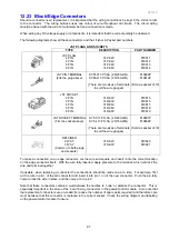
The following diagrams show all these connectors and their Fisher & Paykel part numbers.
JST PLUGS AND SOCKETS
TYPE
DESCRIPTION
PART NUMBER
JST PLUG
2 PIN
4 PIN
6 PIN
8 PIN
YLP-02V
YLP-04V
YLP-06V
YLP-08V
819611
819612
819613
819614
JST PIN TERMINAL
(Fits the plug above)
SYM-01T-P0.5A (26/20 AWG)
SYM-41T-P0.5A (20/16 AWG)
(There are two sizes of terminals
to suit the wire gauges)
819609P
819610P
(Sold as packet of 10)
JST SOCKET
2 PIN
3 PIN
4 PIN
6 PIN
8 PIN
YLR-02V
YLR-03V
YLR-04V
YLR-06V
YLR-08V
819615
819616
819617
819618
819619
JST SOCKET TERMINAL
(Fits the socket above)
SYF-01T-PO.5A (26/20 AWG)
SYF-41T-PO.5A (20/16 AWG)
(There are two sizes of terminals
to suit the wire gauges)
819607P
819608P
(Sold as packet of 10)
RETAINER
2 WAY
3 WAY
(Common to both plugs
and sockets)
YLS-02V
YLS-02V
819620
819621
To make a connection on an edge connector, cut the wire end square and insert it into the correct location
on the edge connector itself. With the wire fully inserted, apply pressure to the terminal, which will lock the
wire and terminal together.
If possible, when replacing a connector the connections should be made one at a time. For example, first
cut the wire in pin 1 of the old connector and insert it into pin 1 on of the new connector. Push the pin fully
home to lock the wire in place, and then move on to pin 2.
Note that these connectors contain a wall between the cavities to ‘code’ or polarize the connector. This is
especially important in the case of the 4 and 6 way connectors in the power/control module. Also note that
the replacement connectors are un-coded (to reduce the number of spare parts required) and therefore care
must be taken that the connector is replaced in the correct socket. Check the wiring diagram and labelling
on the power/control module if unsure.
Summary of Contents for 635 Active Smart
Page 1: ...321144 Service Manual 635 680 790 900 Active Smart Refrigerator Freezer R134a R600a Systems...
Page 2: ...321144 2...
Page 96: ...321144 96 Photo 12 22 5...
Page 100: ...321144 100 Diagram 12 25...
Page 108: ...321144 108 13 11 Embraco Compressor Fitted With External Overload Diagram 13 11...
Page 114: ...321144 114 14 2 Non Ice Water Models Wiring Diagram...
Page 116: ...321144 116 14 4 Ice Water Models Wiring Diagram...
Page 117: ...321144 117 14 5 900 Models Power Control Module Wiring Connections Reciprocating Compressor...
Page 118: ...321144 118 14 6 900 Models Wiring Diagram Reciprocating Compressor...
Page 119: ...321144 119 14 7 900 Models Power Control Module Wiring Connections VC Compressor...
Page 120: ...321144 120 14 8 900 Models Wiring Diagram VC Compressor...
Page 121: ...321144 121 14 9 B Model Wiring Route Diagram 14 9...
Page 122: ...321144 122 14 10 T Model Wiring Route Diagram 14 10...
Page 145: ......


