321144
20
4.2
Internal Air Flow
4.2.1
Ice & Water Models
The
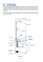
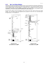
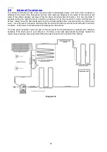
freezer fan draws air through the evaporator and into a duct in the rear wall of the freezer compartment.
This air exits through the fan grill at the top of the freezer compartment. The air behind the freezer coil cover
is also diverted through the divider partition to another fan, which supplies the cold air into the PC
compartment. The amount of air is controlled electronically by two sensors, which in turn regulate, through
the power/control module, the speed of both PC and FC fans to maintain selected temperatures in each
compartment.
Air from the PC returns to the FC evaporator by way of the return air duct, which is built into the divider
partition. This air is drawn across the evaporator by the FC fan motor to be recirculated again throughout
the PC/FC compartments.
Diagram 4.2
Summary of Contents for 635 Active Smart
Page 1: ...321144 Service Manual 635 680 790 900 Active Smart Refrigerator Freezer R134a R600a Systems...
Page 2: ...321144 2...
Page 96: ...321144 96 Photo 12 22 5...
Page 100: ...321144 100 Diagram 12 25...
Page 108: ...321144 108 13 11 Embraco Compressor Fitted With External Overload Diagram 13 11...
Page 114: ...321144 114 14 2 Non Ice Water Models Wiring Diagram...
Page 116: ...321144 116 14 4 Ice Water Models Wiring Diagram...
Page 117: ...321144 117 14 5 900 Models Power Control Module Wiring Connections Reciprocating Compressor...
Page 118: ...321144 118 14 6 900 Models Wiring Diagram Reciprocating Compressor...
Page 119: ...321144 119 14 7 900 Models Power Control Module Wiring Connections VC Compressor...
Page 120: ...321144 120 14 8 900 Models Wiring Diagram VC Compressor...
Page 121: ...321144 121 14 9 B Model Wiring Route Diagram 14 9...
Page 122: ...321144 122 14 10 T Model Wiring Route Diagram 14 10...
Page 145: ......

