321144
22
4.3
Defrost Cycle
4.3.1
R134a System
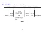
The following table outlines the defrost cycle of an R134a refrigerant system Active Smart
®
refrigerator.
COMPRESSOR
DEFROST ELEMENT
DEFROST ELEMENT
COMPRESSOR
BOTH PC AND FC
TURNS OFF
TURNS ON
TURNS OFF
TURNS ON
FANS TURN ON
DEFROST TIME:
TARGET IS 18 MINUTES OR
SENSOR REACHES 8
O
C.
2 MINUTES
MAXIMUM IS 40 MINUTES
4 MINUTES
30 SECONDS
NORMAL RUN
WARM UP
DEFROST
DRIP TIME
DELAY
BACK TO NORMAL RUN
Diagram 4.3.1
If 40 minutes has elapsed, defrost
would be aborted if defrost sensor
has not reached 8
O
C (46
O
F). If 2
defrosts are aborted, Fault Code 2
is displayed.
Summary of Contents for 635 Active Smart
Page 1: ...321144 Service Manual 635 680 790 900 Active Smart Refrigerator Freezer R134a R600a Systems...
Page 2: ...321144 2...
Page 96: ...321144 96 Photo 12 22 5...
Page 100: ...321144 100 Diagram 12 25...
Page 108: ...321144 108 13 11 Embraco Compressor Fitted With External Overload Diagram 13 11...
Page 114: ...321144 114 14 2 Non Ice Water Models Wiring Diagram...
Page 116: ...321144 116 14 4 Ice Water Models Wiring Diagram...
Page 117: ...321144 117 14 5 900 Models Power Control Module Wiring Connections Reciprocating Compressor...
Page 118: ...321144 118 14 6 900 Models Wiring Diagram Reciprocating Compressor...
Page 119: ...321144 119 14 7 900 Models Power Control Module Wiring Connections VC Compressor...
Page 120: ...321144 120 14 8 900 Models Wiring Diagram VC Compressor...
Page 121: ...321144 121 14 9 B Model Wiring Route Diagram 14 9...
Page 122: ...321144 122 14 10 T Model Wiring Route Diagram 14 10...
Page 145: ......

