321144
32
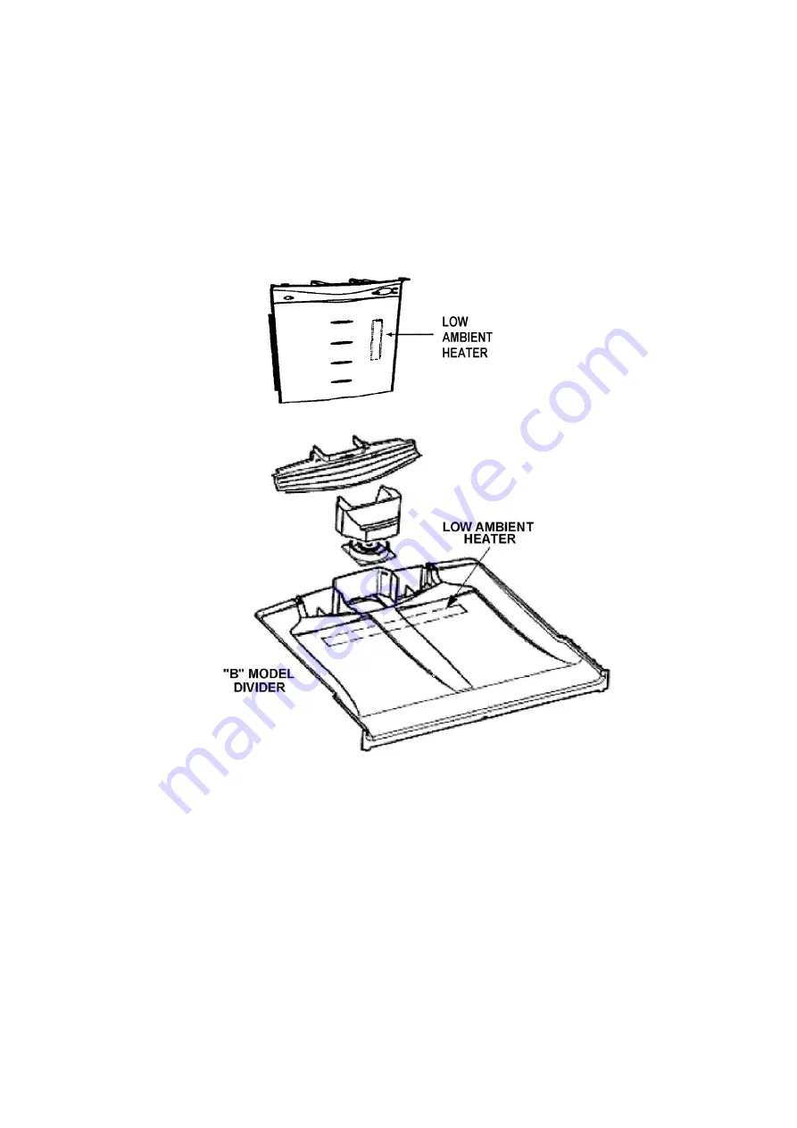
4.19 Low Ambient Heater
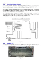
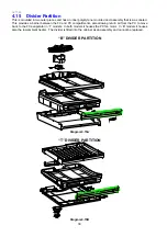
In low ambient temperatures, a 12 Volt, 7 Watt low power heater is used to keep the temperature in the
Provision compartment above freezing. The ambient heater is controlled by the power/control module,
which uses pulse width modulation (PWM) to run the heater at 58% to give 4.1 watts of heat. The ambient
heater is situated in the air duct of the “T” models and in the divider partition on “B” models. The element
has the purpose of warming the area if the ambient becomes too low, hence in the “B” models the element is
on when the compressor cycles off as the crispers could freeze. The low ambient heater in “T” models
operates when the percentage of compressor run time for the last four cycles drops below 30%. It switches
off when the percentage run time increases to above 35%. The heater will always be switched off during
defrosting. There may be less than 4 cycles in the calculation if a defrost has occurred or there were long
cycle times.
“T” MODEL
Diagram 4.19
4.20 PC / FC Fans
4.20.1 “B” Model Fan
There are two 12 Volt DC electrically commutated motors (ECMs). They provide the required cooling air
flow to both compartments. The motor speeds are controlled using a pulse width modulating (PWM)
technique. The power/control module controls the on/off of the compressor, and the fans. The speed of the
FC fan is set, and the speed of the PC fan is regulated using pulse width modulation.
The freezer compartment fan will always be set at the maximum FC fan speed, with the PC fan being
adjusted to meet the requirement of that compartment. We alter the speed of the FC fan under certain
loading conditions. Therefore the PC fan speed will be set at the average speed used from the previous
cycles under normal door openings and loading conditions.
When the compressor is turned on, provided the doors are closed both the fans will also be switched on
except immediately following a defrost cycle, where there is a delay of 5 minutes after the compressor has
started before the FC fan starts.
Summary of Contents for 635 Active Smart
Page 1: ...321144 Service Manual 635 680 790 900 Active Smart Refrigerator Freezer R134a R600a Systems...
Page 2: ...321144 2...
Page 96: ...321144 96 Photo 12 22 5...
Page 100: ...321144 100 Diagram 12 25...
Page 108: ...321144 108 13 11 Embraco Compressor Fitted With External Overload Diagram 13 11...
Page 114: ...321144 114 14 2 Non Ice Water Models Wiring Diagram...
Page 116: ...321144 116 14 4 Ice Water Models Wiring Diagram...
Page 117: ...321144 117 14 5 900 Models Power Control Module Wiring Connections Reciprocating Compressor...
Page 118: ...321144 118 14 6 900 Models Wiring Diagram Reciprocating Compressor...
Page 119: ...321144 119 14 7 900 Models Power Control Module Wiring Connections VC Compressor...
Page 120: ...321144 120 14 8 900 Models Wiring Diagram VC Compressor...
Page 121: ...321144 121 14 9 B Model Wiring Route Diagram 14 9...
Page 122: ...321144 122 14 10 T Model Wiring Route Diagram 14 10...
Page 145: ......

