321144
36
4.23 Basic Operation
4.23.1 Temperature Adjustment – Ice & Water Models
To adjust Compartment Temperatures:
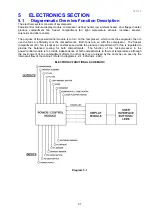
1. Use the
MENU
button to scroll to the
TEMPERATURE
screen on the LCD display.
2. Use the
MENU
button to select the compartment to change.
3. Use the
UP
or
DOWN
arrows to adjust the temperature. The temperature setting will be indicated on
the icon below.
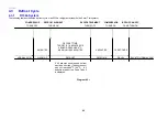
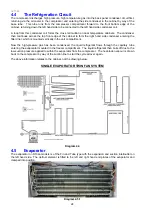
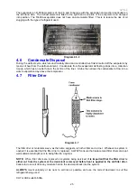
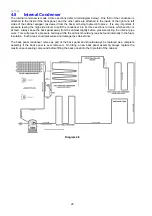
Diagram 4.23.1
4.23.2 Temperature Adjustment – Non-Ice & Water Models
To adjust Compartment Temperatures:
1. Press the
MODE
button.
The provision compartment light on the refrigerator diagram will flash on and off. The temperature
indicator illustrated by a thermometer will show the temperature setting for this compartment.
2. The temperature can be altered by pressing the
TEMPERATURE
UP
or
TEMPERATURE
DOWN
buttons. Fewer LED lights on the thermometer means a cooler temperature.
3. To adjust the freezer temperature press the
MODE
button again. The freezer temperature light will
flash on the refrigerator diagram.
4. The freezer temperature can be altered by pressing the appropriate
TEMPERATURE
UP
or
TEMPERATURE
DOWN
buttons.
Successively pressing the
MODE
button will automatically select between the compartments. A return to the
provision compartment will be accompanied by a longer beep.
LEDs INDICATE APPROXIMATE TEMPERATURE
FC
-12.5
-14.0
-15.5
-17.0
-18.5
-20.0
PC
+ 10
+ 8
+ 6
+ 4
+ 2
0
Diagram 4.23.2
Temperatures shown are average temperatures. One degree C incremental temperature adjustment is
indicated by the “half” lights that illuminate as the temperature up / down button is pressed.
Summary of Contents for 635 Active Smart
Page 1: ...321144 Service Manual 635 680 790 900 Active Smart Refrigerator Freezer R134a R600a Systems...
Page 2: ...321144 2...
Page 96: ...321144 96 Photo 12 22 5...
Page 100: ...321144 100 Diagram 12 25...
Page 108: ...321144 108 13 11 Embraco Compressor Fitted With External Overload Diagram 13 11...
Page 114: ...321144 114 14 2 Non Ice Water Models Wiring Diagram...
Page 116: ...321144 116 14 4 Ice Water Models Wiring Diagram...
Page 117: ...321144 117 14 5 900 Models Power Control Module Wiring Connections Reciprocating Compressor...
Page 118: ...321144 118 14 6 900 Models Wiring Diagram Reciprocating Compressor...
Page 119: ...321144 119 14 7 900 Models Power Control Module Wiring Connections VC Compressor...
Page 120: ...321144 120 14 8 900 Models Wiring Diagram VC Compressor...
Page 121: ...321144 121 14 9 B Model Wiring Route Diagram 14 9...
Page 122: ...321144 122 14 10 T Model Wiring Route Diagram 14 10...
Page 145: ......

