321144
38
5.2
Control and Peripheral Functions
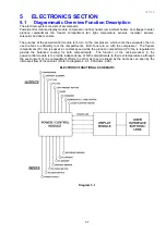
The control system consists of the power/control module located in the unit compartment of the refrigerator,
the slave display module located either in the back of the produce compartment or, in the case of ice and
water models, on the outside of the door, and various sensors and actuators controlled by the power/control
module. The function and brief description of each of these units is defined below (refer to Electronic
Functional Schematic – Diagram 5.1).
5.3
Power/Control Module
There are two types of power/control modules used on these Active Smart
®
cabinets, one for the non-ice &
water cabinets and the other for those cabinets having the ice & water feature.
NOTE:
While the two types of modules are not interchangeable, the ice & water module can be used on a
non-ice and water model.
This module is the electronic brain and control centre of the refrigerator. It contains a microprocessor,
support circuitry and switching devices. The power/control module controls the Provision Compartment (PC)
and Freezer Compartment (FC) temperatures by sensing the temperature and door state and operating the
compressor and fans accordingly. This module also houses the alarm beeper.
The speed of the fans is controlled by pulse width modulation (PWM). The power/control module controls
the motor speed by driving them with short pulses. These pulses vary in duration to change the speed of the
motor. The longer the pulses, the faster the motor turns, and vice versa.
The micro controller in the power/control module uses its internal memory for control; its ROM (Read Only
Memory), for program and fixed constant storage including tables, the RAM (Random Access Memory) for
variable storage and access. It uses an external Electrically Erasable Programmable Read Only Memory (E
2 PROM) for storage of variables and history data which is retained even when the power is turned off.
The power/control module contains a special type of memory device call an E 2 PROM. The information on
the fridge operation, faults and diagnostic information is stored in this memory. They include the
temperature setting, the history of FC, PC temperatures (approx 18 hours), defrost history (the last 12
defrosts) and fault history. This will help the service person find and remedy the cause of failure. All this
memory will be retained even when the fridge is disconnected from mains power supply.
Compressor Start Delay
All Active Smart
®
products will not start the compressor until one minute after both doors are closed, i.e. if
the compressor is off and compartments warm up above their respective switch (turn on) temperatures, and
the doors are open, the compressor will not switch on until one minute after the doors are closed. However,
the compressor will start after 90 seconds irrespective of whether the doors are open or not. (Primarily
introduced for Orthodox Jewish compliance to ensure there is no link between door opening and compressor
starting.)
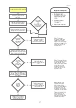
The piezo beeper
is used to signal prolonged door opening and other fault conditions:
1. The PC door alarm sounds if the door is left open for 90 seconds and the FC door alarm sounds if
door is left open after 60 seconds. Both PC and FC alarm will sound every 30 seconds until the door
is closed.
2. If the doors are left open longer than 5 minutes, the alarm will sound continuously and the PC light will
turn off. The alarm will stop with the closing of the door. The light is only reactivated by closing and
opening the door.
3. On non-ice & water models, all electronic faults, when detected, will sound the alarm and the LED’s on
the display module will flash indicating the fault code. The pressing of any button will cancel the alarm
but the fault code will remain until the cabinet has been serviced.
4. On ice & water models, a spanner symbol and LCD fault code will appear automatically if there is a
fault in the temperature measuring system, defrost system, icemaker, fans or low ambient heater.
When the PC door is opened, an alarm will sound. The number of beeps also indicates the fault code.
Pressing any of the control buttons can deactivate this alarm.
Summary of Contents for 635 Active Smart
Page 1: ...321144 Service Manual 635 680 790 900 Active Smart Refrigerator Freezer R134a R600a Systems...
Page 2: ...321144 2...
Page 96: ...321144 96 Photo 12 22 5...
Page 100: ...321144 100 Diagram 12 25...
Page 108: ...321144 108 13 11 Embraco Compressor Fitted With External Overload Diagram 13 11...
Page 114: ...321144 114 14 2 Non Ice Water Models Wiring Diagram...
Page 116: ...321144 116 14 4 Ice Water Models Wiring Diagram...
Page 117: ...321144 117 14 5 900 Models Power Control Module Wiring Connections Reciprocating Compressor...
Page 118: ...321144 118 14 6 900 Models Wiring Diagram Reciprocating Compressor...
Page 119: ...321144 119 14 7 900 Models Power Control Module Wiring Connections VC Compressor...
Page 120: ...321144 120 14 8 900 Models Wiring Diagram VC Compressor...
Page 121: ...321144 121 14 9 B Model Wiring Route Diagram 14 9...
Page 122: ...321144 122 14 10 T Model Wiring Route Diagram 14 10...
Page 145: ......

