321144
42
6.5
VCC-3 Inverter With Diagnostic Function
This function has been added to the new generation of VCC inverter in order to help Service Technicians
diagnose faults.
6.5.1
Diagnostic Procedures
Diagnostic codes for VCC-3 inverter.
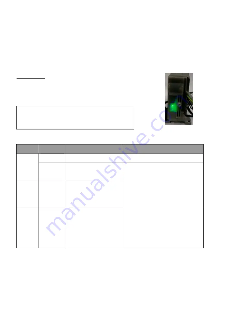
Through a translucent front cover, the VCC-3 inverter flashes a green LED to indicate a fault due to inverter failure,
compressor failure or lack of signal from the power/control module.
The LED flashes every 0.5 seconds inside a flash cycle, and each flash lasts 125 milliseconds.
Flashing Cycles:
Flash Code 1: 1 cycle every 15 seconds
(1 flash every 15 seconds).
Flash Code 2: 2 cycles every 5 seconds
(2 flashes every 5 seconds).
Flash Code 3: 3 cycles every 5 seconds
(3 flashes every 5 seconds).
Flash Code 4: 4 cycles every 5 seconds
(4 flashes every 5 seconds).
VCC-3 Diagnostic Codes
1 Flash
- No failure detected.
2 Flashes - No signal from power/control module.
3 Flashes - Inverter failure.
4 Flashes - Compressor failure.
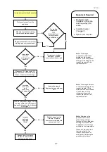
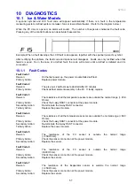
Figure 1 – Label on the VCC-3 inverter box
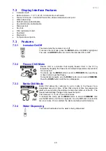
Figure 2 – LED position on
the inverter box
Code
Compressor
Status
Probable Root Causes
Service Action
ON
No Fault Detected.
All OK with the inverter.
¾
Check other refrigerator components in
case the system is not refrigerating.
1 Flash
(every 15
seconds)
OFF
No signal from
power/controller module.
- No power to power/control
module?
¾
Unplug VCC from the power supply and
wait 2 minutes.
¾
Reconnect the VCC to the power supply
and wait for 12 minutes.
2 Flashes
(every 5
seconds)
OFF
No signal from
power/controller module.
¾
Check frequency cable connection.
¾
Check the power to the power/control
module.
If the frequency cable connection and
power/control module are OK:
¾
Replace the inverter.
3 Flashes
(every 5
seconds)
OFF
Compressor / inverter cable
interrupted (open circuit).
- Inverter damaged?
- Compressor winding open
circuit?
¾
Check inverter/compressor cable is
connected.
¾
Check compressor winding resistance
across all three terminals of the
compressor fusite.
If the winding resistances are with in
specification and both inverter &
compressor cables are OK:
¾
Replace the inverter.
Summary of Contents for 635 Active Smart
Page 1: ...321144 Service Manual 635 680 790 900 Active Smart Refrigerator Freezer R134a R600a Systems...
Page 2: ...321144 2...
Page 96: ...321144 96 Photo 12 22 5...
Page 100: ...321144 100 Diagram 12 25...
Page 108: ...321144 108 13 11 Embraco Compressor Fitted With External Overload Diagram 13 11...
Page 114: ...321144 114 14 2 Non Ice Water Models Wiring Diagram...
Page 116: ...321144 116 14 4 Ice Water Models Wiring Diagram...
Page 117: ...321144 117 14 5 900 Models Power Control Module Wiring Connections Reciprocating Compressor...
Page 118: ...321144 118 14 6 900 Models Wiring Diagram Reciprocating Compressor...
Page 119: ...321144 119 14 7 900 Models Power Control Module Wiring Connections VC Compressor...
Page 120: ...321144 120 14 8 900 Models Wiring Diagram VC Compressor...
Page 121: ...321144 121 14 9 B Model Wiring Route Diagram 14 9...
Page 122: ...321144 122 14 10 T Model Wiring Route Diagram 14 10...
Page 145: ......


