321144
53
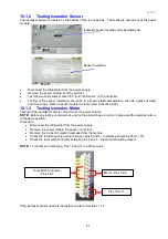
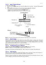
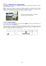
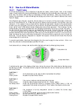
Bin full of Ice
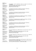
Lever sensing if ice bin is
full.
If bin is not full, icemaker
continues rotation to eject
ice.
8.4
Safety First
•
When first placed into operation, discard the first bin of ice, as this will remove any impurities that may
have been in the water system.
•
Do the same after vacations or extended periods when ice is not used.
•
Ice cubes, when not used, will become cloudy, will shrink, and will taste stale. The ice bin will need to
be emptied and cleaned periodically.
•
Avoid contact with moving parts of the ejector mechanism.
•
Do not place fingers on the automatic ice making mechanism while the refrigerator is turned on.
8.5
Icemaker Fill Tube Heater
There is a heater located under the fill tube nozzle to prevent the fill tube from freezing. It is connected in
series with the low ambient heater.
8.6
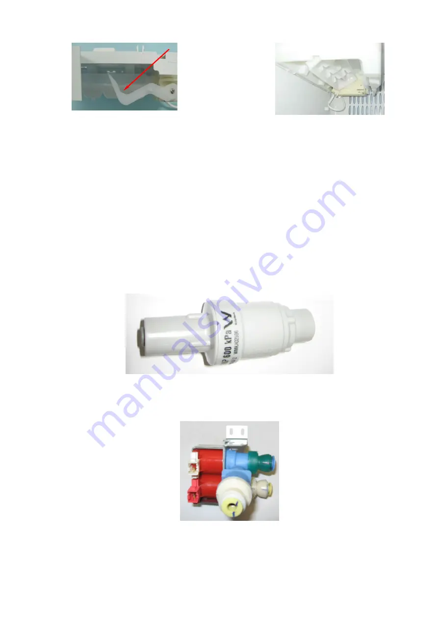
Pressure Limiting Valve
The pressure limiting valve must be fitted between the water supply tap and the inlet hose to the refrigerator
to limit the pressure of the water supply. It must be fitted a minimum of 250mm (10 inches) from the tap to
prevent water hammer.
The valve has an outlet pressure of 600Kpa. The flow direction is marked by an arrow on the side of the
valve.
Diagram 8.6
8.7
Water Inlet Valves
The water inlet valves are rated at 16 watts and have a flow rate of 2 litres (0.5 gallon) per minute. Both
coils are coloured red. The earlier water inlet valves were coloured blue and rated at 10 watts. The16-watt
valve is not interchangeable with the older 10-watt valves.
Diagram 8.7
Summary of Contents for 635 Active Smart
Page 1: ...321144 Service Manual 635 680 790 900 Active Smart Refrigerator Freezer R134a R600a Systems...
Page 2: ...321144 2...
Page 96: ...321144 96 Photo 12 22 5...
Page 100: ...321144 100 Diagram 12 25...
Page 108: ...321144 108 13 11 Embraco Compressor Fitted With External Overload Diagram 13 11...
Page 114: ...321144 114 14 2 Non Ice Water Models Wiring Diagram...
Page 116: ...321144 116 14 4 Ice Water Models Wiring Diagram...
Page 117: ...321144 117 14 5 900 Models Power Control Module Wiring Connections Reciprocating Compressor...
Page 118: ...321144 118 14 6 900 Models Wiring Diagram Reciprocating Compressor...
Page 119: ...321144 119 14 7 900 Models Power Control Module Wiring Connections VC Compressor...
Page 120: ...321144 120 14 8 900 Models Wiring Diagram VC Compressor...
Page 121: ...321144 121 14 9 B Model Wiring Route Diagram 14 9...
Page 122: ...321144 122 14 10 T Model Wiring Route Diagram 14 10...
Page 145: ......


