321144
61
10.1.2 Testing Icemaker Sensor
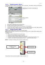
The icemaker sensor is located on the bottom of the ice cube tray. The testing is carried out at the power
module.
Icemaker sensor located under insulated pad.
Sensor Insulation.
•
Disconnect the refrigerator from the power supply.
•
Remove the power module from the product.
•
Test the two white wires marked “0V” and “Ice Sensor” on the controller.
•
Testing of the sensor resistance should be in a known stable temperature, such as a glass of water
full of ice cubes. Refer to sensor resistance table (refer to Section 4.22).
10.1.3 Testing Icemaker Motor
Testing of the icemaker motor is carried out at the power module.
NOTE:
Before any testing is carried out, ensure the product has an ice bin in place and the icemaker arm is
in the down position.
Procedure:
•
Disconnect the refrigerator from the power supply.
•
Remove the power module to expose connectors.
•
Remove the connector marked
Icemaker
from the module.
•
Check the resistance of the motor between pins 5 and 6 – resistance should be 35
Ω
+/- 5%.
•
Check the tact switch continuity between pins 4 and 7 – the switch should be closed.
NOTE:
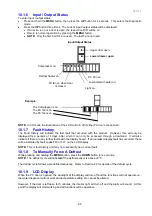
To identify pin numbering, Pins 10 and 11 are White wires
If the icemaker sensor needs to be replaced, refer to Section 11.1.4.
Pins 10 & 11
Motor - Pins 5 & 6
Tact switch continuity –
Pins 4 & 7
Summary of Contents for 635 Active Smart
Page 1: ...321144 Service Manual 635 680 790 900 Active Smart Refrigerator Freezer R134a R600a Systems...
Page 2: ...321144 2...
Page 96: ...321144 96 Photo 12 22 5...
Page 100: ...321144 100 Diagram 12 25...
Page 108: ...321144 108 13 11 Embraco Compressor Fitted With External Overload Diagram 13 11...
Page 114: ...321144 114 14 2 Non Ice Water Models Wiring Diagram...
Page 116: ...321144 116 14 4 Ice Water Models Wiring Diagram...
Page 117: ...321144 117 14 5 900 Models Power Control Module Wiring Connections Reciprocating Compressor...
Page 118: ...321144 118 14 6 900 Models Wiring Diagram Reciprocating Compressor...
Page 119: ...321144 119 14 7 900 Models Power Control Module Wiring Connections VC Compressor...
Page 120: ...321144 120 14 8 900 Models Wiring Diagram VC Compressor...
Page 121: ...321144 121 14 9 B Model Wiring Route Diagram 14 9...
Page 122: ...321144 122 14 10 T Model Wiring Route Diagram 14 10...
Page 145: ......

